Loading Data
Tecplot 360 can load data from files on your local machine or accessible from a network file share using modules called loaders, each of which understands data in a particular format. A number of loaders are provided with Tecplot 360 for commonly-used CFD and general scientific and engineering formats as well as various Tecplot formats. See Loading Data Using a Loader.
You can also load data from Tecplot SZL Server, a lightweight module you can install on a remote Linux host (such as a compute cluster) to get access to your data when it is not practical to move it off the cluster to a local drive or to a network file share, and when you cannot reasonably run Tecplot 360 on the remote host over a remote desktop setup.
To set up Tecplot SZL Server see "Installing SZL Server" in the Tecplot 360 Installation Guide. To open data hosted by SZL Server, see Loading Remote Data using Tecplot SZL Server.
Loading Data Using a Loader
Use the command to load a data file using the Load Data dialog, shown below.
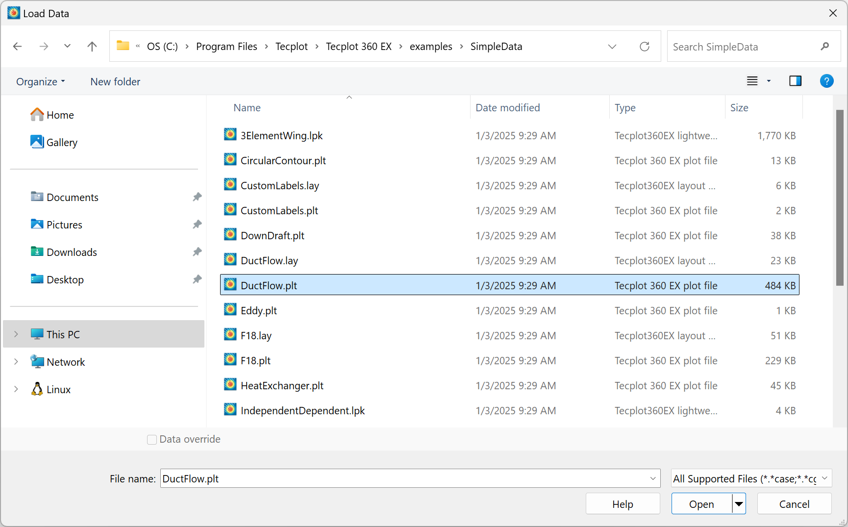
Normally, this dialog works slightly differently on Windows and non-Windows platforms. The controls at the bottom of the dialog are different. For example, this is the lower portion of the dialog as seen on Linux.

On Windows, you can switch to this version of the Load Data dialog by choosing . Using this version of the dialog on Windows may be slower to navigate depending on your network; however, you may want to try it if you regularly load multiple data files from more than one directory.
On any platform, you may use the Load Data dialog to navigate to the file you wish to open, or simply type or paste the filename or the full pathname of the file in the File Name field.
| If the file you are loading is a Tecplot-format file, you may also load it by simply dragging it from your file manager (e.g. Windows Explorer or Mac Finder) into the Tecplot 360 workspace, bypassing the Load Data dialog entirely. You can also load data files via the macro language; refer to $!READDATASET in the Scripting Guide for details. |
The menu below the file list allows you to choose a data loader corresponding to the format of data file that you wish to load, or you may select All Files to see all the files in the directory and have Tecplot 360 automatically choose a loader for you if possible. When you choose a loader, the file list changes to show only files that can be loaded by that loader.
| If the name of the file you are trying to load has a non-standard extension, type the extension in the File Name field like "*.foo", then press Enter to show all files having this filename extension. You may also enter "*.*" to show all files regardless of their extension, or choose from the menu to have Tecplot 360 try to determine which loader is needed. |
-
If the chosen loader needs only a single file, simply navigate to and select the file you want to load in the file list and click .
-
If the chosen loader supports or requires loading more than one file at once, or you are choosing from or , you may select multiple files. On Windows (using the standard version of the Load Data dialog), you can choose additional files by holding down Control or Shift while clicking the second and subsequent files in the dialog, then clicking .
On other platforms (or on Windows using the extended version of the Load Data dialog), the button becomes enabled. Select each file to be loaded and click to add it to the Additional Files list. You may choose files from more than one directory. You may also remove selected files from the list by clicking the or button. Click to open all the files using the loader you chose.
When using or , all of the files should be in the same format. If the loader for that format cannot load multiple files, you must load them individually, appending the second and subsequent files.
-
Some file formats are very flexible, so you may need to specify exactly how the data was written in order for Tecplot 360 to load it correctly. Some loaders always display an options dialog, since they are needed almost every time. Others only display an options dialog when you request it. On Windows (using the standard dialog), click the menu triangle next to the Open button and choose instead of clicking after selecting your file(s). On non-Windows platforms (or when using the extended dialog on Windows), an checkbox becomes enabled and may be selected before clicking . The loader’s options dialog is then displayed before loading the selected file(s).
Available file formats include:
Loading by Position
In most CFD data formats, it is valid to have multiple variables with the same name. When loading such a file, Tecplot 360 warns you that this situation exists and offers to load the variables by position: each variable will be identified by the order in which it appears in the file rather than by its name. This may make some aspects of working with the data different or more complicated.
For example, when manipulating data using equations, you must use the V# syntax to
refer to such duplicate variables, rather than the {VariableName} syntax, as the
latter cannot uniquely identify the variable. (See Data Alteration through Equations.) Macros and
Python scripts may also be affected.
When possible, we advise obtaining a data file with a unique and consistent name for each variable, for example by adjusting your solver’s configuration.
Appending or Replacing Data
You may append new data to your dataset at any time by choosing . You cannot append a grid file that contains only FE connectivity data without appending a solution file along with it. In addition, to append a solution file you must also append a grid file at the same time. In this case, the grid file must be loaded before the solution file.
Some loaders allow you to choose how you wish to append or replace data.
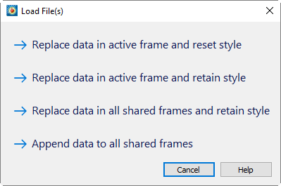
Depending on the circumstances, you may have the following choices:
- Replace Data in Active Frame and Reset Style
-
The new data is loaded in place of the existing data. The plot styles are reset to their defaults, as if the new data was loaded immediately after starting up Tecplot 360.
- Replace Data in Active Frame and Retain Style
-
The new data is loaded in place of the existing data. The plot styles in effect for the existing data are applied to the new data as best as possible and in some cases some style settings may need to be turned off or reassigned. The configuration option
$!COMPATIBILITY USENAMESFORVARIABLEASSIGNMENTS, when set to TRUE will make style settings match variable assignments based on the variable names, regardless of their position in the old and new datasets. If$!COMPATIBILITY USENAMESFORVARIABLEASSIGNMENTSis set to FALSE then the variable offsets from the old style assignments will be used with the new data regardless of the old and new variable names. This option works best when the incoming data is similar to the existing data. - Replace Data in All Shared Frames and Retain Style
-
This is the same as "Replace Data in Active Frame and Retain Style" except the same operations and rules are applied to all frames that share the same dataset with the active frame.
- Append Data to All Shared Frames
-
The active dataset is shared among multiple frames. Choose this option to append the newly loaded data in all the frames. Default plot styles are used.
- Append Data to Active Frame
-
Choose this option to append the newly loaded data in the current frame.
- Replace
-
When loading a layout, replaces the existing layout with the new one.
- Append
-
When loading a layout, creates new frames for the dataset referenced in the new layout.
- Cancel
-
Do not load the data and return to the Tecplot 360 workspace.
Loading and Combining Variables from Multiple Files
In Tecplot 360, you can load multiple data files in two different ways:
-
All at once by choosing all the files in the Load Data Files dialog.
-
By appending data to the data that has already been loaded.
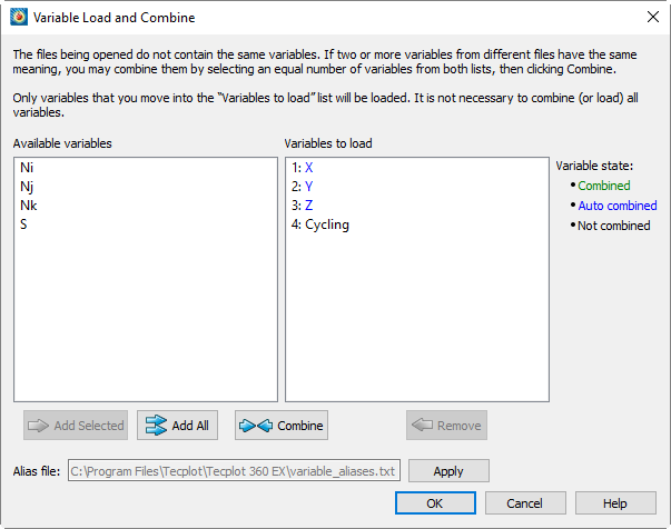
The Variable Load and Combine dialog appears when loading multiple data files in certain formats, whether you load the files all at once or append new data to previously-loaded data, if the names of the variables in the data files do not match. The dialog allows you tell Tecplot 360 which variables (if any) have the same meanings across the files, as well as which variables should not be loaded at all.
This feature works only with data in the following formats:
-
Tecplot - text (.dat), binary (.plt), and subzone (.szplt)
-
CGNS
-
EnSight
-
Excel
-
HDF and HDF5
-
Text (using the Text Spreadsheet or General Text loader)
-
TRIX
-
VTK
The Variable Load and Combine dialog appears only when the files you are loading do not all contain exactly the same variable names (or, when appending, if the variable names in the file being loaded do not exactly match those of the data already loaded). When all variable names match in the files being loaded, this dialog does not appear; instead, Tecplot assumes that all the variables have the same meaning in all the files.
| If a file you are loading or appending has multiple variables with the same name, Tecplot 360 asks if you want to load them by position. See Loading by Position. When loading by position, you cannot combine variables (and do not need to). |
The dialog allows you to indicate that variables with different names have the same meaning (referred to as combining the variables) in two different ways.
-
Select variables having the same meaning, one in each list, then click .
-
Apply a previously-defined variable alias file that indicates which variable names have the same meaning.
The two methods can also be used together. For example, you might first apply a variable alias file that deals with the most common equivalent variables in your typical data sets, then clean up any remaining variables (uncommon variables, or variables that don’t always have a well-defined meaning) by hand.
The dialog has the following parts:
-
The Available Variables list initially displays all the variables declared in the files you are loading. As you choose variables to combine or load, they move to the Variables to Load list. Any variables remaining in the Available Variables list when you click are not loaded.
-
The Variables to Load list displays variables that are slated to be loaded in the current load operation. If you are appending data, variables that have already been loaded in previous load operations also appear here. Variables are colored according to the following rules:
- Black
-
Variable is not combined; it is either already loaded, or will be loaded
- Blue
-
Variable appears under the same name in multiple files and has been automatically combined
- Green
-
Variable has different names in different files and has been combined by the user, either using the button or by applying a variable alias file
-
The button moves a variable from the Available Variables list to the Variables to Load list, adding it to the set of variables that will be loaded in the current operation. The added variable’s name appears in black. By default, variables that are unique to one file are not loaded.
-
The button moves all variables listed in the Available Variables list to the Variables to Load list, indicating that you want to load all of them in the current operation. The variable names appear in black.
-
The button combines the variable selected in the Available Variables list with the variable selected in the Variables to Load list, indicating that the variables have the same meaning. The variable is given a name derived from both the selected variables, and this name appears in the Variables to Load list and is colored green. See Combining Variables Manually.
-
The button removes the selected variable from the Variables to Load list, if possible. If the variable is already part of the current data set (that is, you are appending data, and the variable is from a previous load operation), it cannot be removed.
When removing a combined variable, all the original variables that were combined are separated and moved back to the Available Variables list, again except for any which have already been loaded from a previous operation.
-
The button applies a variable alias file to the variables being loaded, combining variables if they are defined in the file as having the same meaning as another variable. See Creating and Using a Variable Alias File.
-
Click to proceed with loading after setting up the variable combining the way you want it.
Variables that have the same name are automatically combined, as this is almost always what you will want to have happen. They appear in blue in the Variables to Load list. If you do not want this to happen, load the files one at a time and, before loading the file with duplicate variable names, rename the existing variables you do not want to combine with newly-loaded variables of the same name. (You can rename variables by double-clicking them in the Data Set Information dialog.
Combining Variables Manually
To combine two variables manually, telling Tecplot 360 that they have the same meaning, you select the first variable in the Available Variables list and the second in the Variables to Load list, then click the button. The combined variable is added to the Variables to Load list and given a name consisting of both original variable names separated by a semicolon.
If the variables to be combined are in the Available Variables list, as may be the case when loading all the files at once instead of appending, select one in the Available Variables list and click to select it to be loaded. Then combine them as above.
If there are more than two variables that have the same meaning, combine the first two, then select the combined variable in the Variables to Load list and combine it with the next variable having the same meaning in the Available Variables list as above.
You may combine multiple sets of variables at a time. If you select more than one variable in the Available Variables list, and the same number in the Variables to Load list, clicking Combine combines the first selected variable from the Available Variables list with the first selected variable from the Variables to Load list, the second with the second, and so on.
You may not combine variables from the same file.
Creating and Using a Variable Alias File
The variable_aliases.txt file found in the Tecplot 360 installation directory lists sets of variables that should be considered equivalent. See Custom Files loaded on Startup for information about how variable aliases are loaded.
The variable_aliases.txt file must begin with a !VA 1 line to indicate that
it is a variable alias file (format version 1). On subsequent lines, the character
indicates the beginning of a comment; everything following the on a line is
ignored. Variable aliases are specified by listing the equivalent names on a line
separated by semicolons. For example:
#!VA 1
p;press;pressure
t;temp;temperature # temperature variables in Celsius
m;mach
a;alpha;aoa # angle of attack in radians
b;beta;aos # angle of sideslip in radians
Variable names found in this file are case-insensitive. Excess whitespace is ignored.
When you click , Tecplot 360 combines variables as indicated in variable_aliases.txt. Where two or more files contain variables whose names appear on the same line, these variables are combined, and the resulting Tecplot 360 variable is given a name containing the original variable names (as they appear in the datasets being loaded) separated by semicolons. The new variables then appear in the Variables to Load list in the dialog.
For example, if you load two files with the variables "P" and "Pressure," and the lines shown above appear in the variable_aliases.txt file, when you click , these two variables appear in the Variables to Load list as a single variable called either "P;Pressure" or "Pressure;P" depending on the order in which the files were loaded.
If multiple lines in variable_aliases.txt might apply to the data sets being loaded, these conflicts are resolved based on the order in which the files are loaded. For example, if you load three files containing variables "M," "Mach," and "Mass," in that order, and variable_aliases.txt contains lines equating "M" with "Mach" and also "M" with "Mass," the resulting data set would have a variable named "M;Mach" and a second variable "Mass." Because the file containing the variable "Mach" was loaded before the file containing the variable "Mass," "M" was combined with "Mach" when that file was loaded and cannot also be combined with "Mass."
You may change the names of combined variables after loading the data by double-clicking the variable in the Data Set Information dialog ().
All Files and All Supported Files
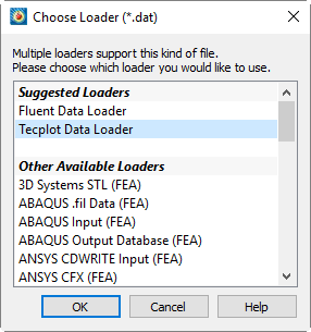
With and , Tecplot 360 tries to automatically choose a loader based on the names of the files you select.
With , you see literally all of the files in the directory you’re browsing. With , you see the files that Tecplot 360 knows it can load using any of the installed loaders, based on the files' names, but excluding other files. Either choice allows you to load files without having to specify in advance what loader will be used.
These options are particularly useful if you regularly work with multiple data file formats, or (in the case of All Files) if your data files often have unconventional names, such as a nonstandard or absent filename extension.
If the names of the selected files unambiguously indicate a single data file format, the appropriate loader is automatically chosen and the data is loaded without further ado. If more than one loader might be able to open the files, or if the files chosen do not have names that are recognized as belonging to a particular loader, the Choose Loader dialog appears. This dialog may recommend one or more loaders in a "Suggested Loaders" section at the top of the list. Choose the loader to be used, then click .
All selected files must be in the same format.
CGNS Loader
The CGNS Loader supports files created with CGNSLib Version 4.1.2 or earlier with either ADF or HDF5 internal representation. You can choose to load either all or specific bases, zones, and solutions into Tecplot 360 zones. You can also select field variables individually, or define index ranges to load specific sub-zone blocks or planes for structured-grid zones.
The dialog has the following options:
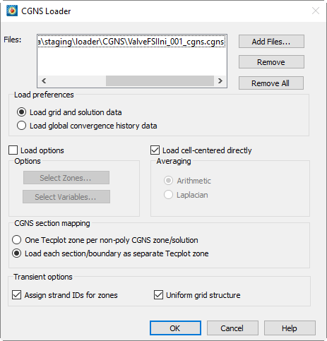
- Files
-
Click the buttons to add or remove files from the list of files to be loaded.
- Load Preference
-
Choose to load either grid and solution data, or global convergence history data. If a file contains both types of information, they must be loaded separately.
- Specify Options
-
Active when a valid file is entered or selected. This option allows you to control the data loaded from your CGNS file, including loading only particular zones, field variables, or partial zones.
If "Specify Options" is not selected, every base, zone, solution, and variable is loaded into Tecplot 360. - Select Zones
-
Launches the Load CGNS Options: Zones Dialog, which allows you to select specific zones and partial zones to load.
- Select Variables
-
Launches the Load CGNS Options: Variables Dialog, which allows you to select specific field variables to load. Grid variables are always loaded automatically.
- Load Cell-centered Data Directly
-
Toggle-on to load cell-centered data directly (default). When the option is toggled-off, cell-centered data will be averaged to the nodes (using the averaging method specified below).
- Averaging
-
This option is available only if "Load Cell-centered Directly" is not selected. When the field variables are stored at cell centers, either Laplacian averaging or arithmetic averaging may be used to average the cell data to the nodes they surround. This can result in a bias at the boundary nodes. Arithmetic averaging is automatically used for ordered/structured zones. When available, Rind data is used in the averaging.
- CGNS Section Mapping
-
CGNS files sometimes have multiple node-maps (referred to as sections) for each finite element zone. A zone may contain sections with different cell types and cell dimensions.
- One Tecplot zone per non-poly CGNS zone/solution (default)
-
All non-polytope sections with the same zone cell dimension will be combined into one zone in Tecplot 360.
- Load each section/boundary as separate Tecplot zone
-
A separate zone will be created in Tecplot 360 for each section or boundary regardless of cell dimension.
- Transient Options
-
- Assign Strand IDs for zones
-
Toggle-on to assign Strand IDs to transient zones. Refer to Time Aware for more information on working with transient data.
- Uniform grid structure
-
Toggle-on to use the grid from the first time step for all time steps, saving time and memory. Toggle-off if more than one grid is used.
CGNS Support Notes
The CGNS loader can load IJK-indexed, finite element, and polytope (polygonal/polyhedral) data, the latter denoted with NGON/NFACE sections in the data file. Polygonal sections may not be combined with sections of other types.
CGNS Boundary Conditions can be loaded for both structured and unstructured data with the exception that unstructured boundaries will only be loaded if they have corresponding sections.
Only CGNS bases and zones with valid grids can be read by the CGNS Loader. For unstructured grids, the CGNS Loader supports BAR_2, TRI_3, QUAD_4, TETRA_4, PYRA_5, PENTA_6, HEXA_8, MIXED element types and their combinations on every section. However, the CGNS Loader does not support higher-order element types. Unstructured sections that are cell-centered and have more cells than are declared in the CGNS Zone_t node will be ignored.
Only vertex and cell-centered field variable locations are supported. Cell-centered data can be read in directly or averaged to the nodes when the file is read. For cell-centered structured grids, arithmetic averaging is used. Rind data is used in the averaging if available. For cell-centered unstructured grids, either Laplacian averaging or arithmetic averaging can be selected to average the cell data to the surrounding nodes.
The CGNS Loader assigns strand IDs for zones by grouping them into time steps based on their solution times. The first zone from each time step is assigned to strand 1, the second to strand 2, and so on until all zones have been assigned to a strand. CGNS Base Names and Zone Names are converted to zone auxiliary data under the keys "CGNS.CGNSBase_t" and "CGNS.Zone_t," respectively.
For CGNS files with an HDF5 internal representation, Tecplot 360 uses HDF5 library version 1.12.0.
|
The CGNS loader, based on CGNS 4.1 is not compatible with CGNS 3.3 files backed by HDF5 1.10 due to a change to the CGNS library. Ensure your CGNS library is using a compatible version of HDF5. See CGNS bugs here: |
| The CGNS 4.1 library has reduced performance (~10%) with ADF backed files. For best performance convert CGNS files to HDF5. |
Load CGNS Options: Zones Dialog
Zones in Tecplot 360 are not always equivalent to CGNS zones. The dialog allows you to specify zones to load from CGNS data files.
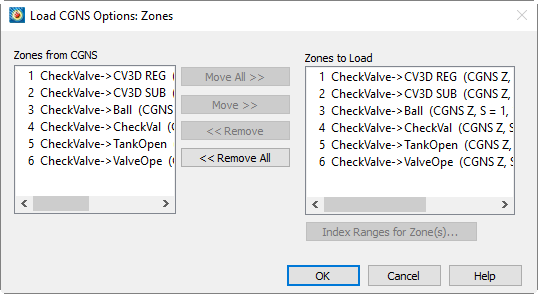
Each solution for a CGNS zone is considered a unique zone in Tecplot 360. The CGNS base (B), zone (Z), and solution (S) hierarchy orders the zones. The integer preceding the word Zone is the internal zone number assigned to that zone. The integer following Zone represents the order the zone was found in the CGNS file.
Table 1 describes the zone description listed in the dialog box. The zone description includes the CGNS hierarchy information. "CGNS B, Z, S =" followed by three integers representing the CGNS order for the base, zone, and solution, respectively. "CGNS Z, S =" and two integers are displayed if a single base is found. The description also indicates whether the zone is ordered (structured) or finite element (unstructured). I, J, and K-dimensions are provided for ordered zones; the number of nodes and elements are provided for finite element zones.
int |
Zone |
int |
{CGNS B, Z, S = x, y, z} |
[Ordered, FE] |
|---|---|---|---|---|
internal zone number |
"Zone" |
order in CGNS file |
x = Base number |
"Ordered" |
By default, all zones are selected for reading and displayed in Zones to Load. Use the , , , or buttons to edit the list.
The dialog allows you to specify a sub-set of the selected ordered/structured zone(s) to be loaded, or define a block, plane, or line of points for extraction on loading. To load a partial zone or sub-zone, highlight the zone of interest in region of the dialog, and select the button.
Each index requires Start, End, and Skip values. Start and End points are always loaded. If multiple zones are selected prior to calling up the dialog, "Mx" (the maximum value for each zone) is the default value for End. You may enter any value for End. However, if the value is greater than the maximum index for a zone, End is replaced by the maximum index.
For multi-dimensional zones, more than one point must be specified to load for the I and J-directions. If the inputs for Start, End, and Skip result in a single point in either direction, an error message appears.
Load CGNS Options: Variables Dialog
The dialog includes the Variables from CGNS and Variables to Load boxes.
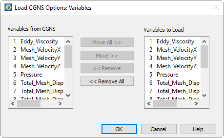
The "Variables from CGNS" list includes all field variables in the CGNS data file, independent of their zone(s). The "Variables to Load" list contains the field variables that have been selected to be loaded into Tecplot 360. Initially, both lists are the same. A variable number is assigned to each CGNS field variable that appears in the "Variables to Load" list.
Because Tecplot 360 requires every zone to have the same number of variables, each zone that is loaded into Tecplot 360 will include every variable in the "Variables to Load" list (regardless of whether the zone included that field variable in the CGNS file). The variables that were not originally in the zone will be set to zero. The field variables that do not appear in the "Variables to Load" list will not have a variable number assigned to them.
Use the , , , or buttons to edit the Variables to Load list.
Macro Commands for the CGNS loader
The syntax for loading CGNS data files with the Tecplot macro language is as follows:
$!READDATASET
' "STANDARDSYNTAX" "1.0"
"...any of the name value pairs in the following table..." '
DATASETREADER = 'CGNS LOADER'
Each name/value pair should be in double quotes. Refer to the Scripting Guide for details on working with the Tecplot macro language.
| Keyword | Values | Default | Notes |
|---|---|---|---|
STANDARDSYNTAX |
"1.0" |
n/a |
Must be the first instruction. |
FILENAME_CGNSFILE |
"filename" |
n/a |
The name of the file to load. |
FILELIST_CGNSFILES |
"filenames" |
n/a |
Option to load multiple files. Syntax: "FILELIST_CGNSFILES n filenames" where n is the number of files to be loaded and filenames is a list of CGNS files delimited by spaces. |
LoaderVersion |
"V3" |
n/a |
The loader version to use; V3 is current |
CgnsLibraryVersion |
"4.1.2" |
n/a |
The CGNS library that was used when loading the data. The CGNS loader uses this information to determine whether any version incompatibility exists that may affect how the data file is loaded, and warns the user in that case. |
AverageToNodes |
"Yes" |
"Yes" |
Used to average the cell data to the nodes they surround. |
AveragingMethod |
"Laplacian" |
"Arithmetic" |
If AverageToNodes is set to "yes", specify the AveragingMethod to use. |
SectionLoad |
"Combine" |
"SeparateZones" |
CGNS files may have multiple node-maps (or sections) for each finite element zone. If you specify "Combine", all sections are combined with the zone cell-dimension into one zone. If you specify "SeparateZones", a separate zone is created for each section or boundary regardless of cell dimension. |
LoadBCs |
"Yes" |
"No" |
Specify whether to load the boundary conditions. For unstructured data, boundary conditions will always be loaded. |
AssignStrandIDs |
"Yes" |
"Yes" |
Set to "Yes" to automatically assign the strand IDs to your data file. |
ZoneList |
like "Z1, Z2, + Z3-Z7, …" |
All zones |
Specify the zone number(s) of the zone(s) you wish to load. |
VarNameList |
like "V1, V2, + V3-V7, …" |
All variables |
Specify the variable number(s) of the variable(s) you wish to load. |
IIndexRange |
"Zn, Min, + Max, Skip" |
All |
If you are loading a subset of zones, you may specify the index ranges for each zone. Specify the zone number, minimum, maximum, and skip value for each index. Set Zn to "0" to apply the index ranges to all zones. |
JIndexRange |
"Zn, Min, + Max, Skip" |
All |
|
KIndexRange |
"Zn, Min, + Max, Skip" |
All |
|
LoadConvergenceHistory |
"Yes" |
"No" |
Loads global convergence history data in the CGNS file, if any, rather than grid and solution data. |
UniformGridStructure |
"Yes" |
"Yes" |
If "Yes," the same grid is assumed for all timesteps and only the first timestep’s grid is loaded. If "No," the grid is loaded for each timestep. |
CONVERGE CGNS File Loader
Use the CONVERGE CGNS loader to load post*.cgns files produced by CONVERGE. This loader does not have any Advanced Options and will load all supplied variables. Multiple files may be loaded via the Load Data dialog. Multiple files will be separated into separate zones in Tecplot.
Macro Commands for the CONVERGE CGNS loader
The syntax for loading CONVERGE CGNS data files with the Tecplot macro language is as follows:
$!READDATASET ' "STANDARDSYNTAX" "1.0"
"..any of the name value pairs in the following table..." '
DATASETREADER = 'CONVERGE CGNS File Loader'
Each name/value pair should be in double quotes.
| Keyword | Values | Default | Notes |
|---|---|---|---|
STANDARDSYNTAX |
"1.0" |
n/a |
Must be the first instruction. |
FILENAME_FILE |
"filename" |
n/a |
The name of the file to load. |
FILELIST_DATAFILES |
"filenames" |
n/a |
Option to load multiple files. Syntax: "FILELIST_DATAFILES n filenames" where n is the number of files to be loaded and filenames is a list of CONVERGE CGNS files delimited by spaces. |
CONVERGE HDF5 File Loader
Use the CONVERGE HDF5 loader to load post*.h5 files produced by CONVERGE. This loader does not have any Advanced Options and will load all supplied variables. Multiple files may be loaded via the Load Data dialog. Multiple files will be separated into separate zones in Tecplot.
Macro Commands for the CONVERGE HDF5 loader
The syntax for loading CONVERGE HDF5 data files with the Tecplot macro language is as follows:
$!READDATASET ' "STANDARDSYNTAX" "1.0"
"..any of the name value pairs in the following table..." '
DATASETREADER = 'CONVERGE HDF5 File Loader'
Each name/value pair should be in double quotes.
| Keyword | Values | Default | Notes |
|---|---|---|---|
STANDARDSYNTAX |
"1.0" |
n/a |
Must be the first instruction. |
FILENAME_FILE |
"filename" |
n/a |
The name of the file to load. |
FILELIST_DATAFILES |
"filenames" |
n/a |
Option to load multiple files. Syntax: "FILELIST_DATAFILES n filenames" where n is the number of files to be loaded and filenames is a list of CONVERGE HDF5 files delimited by spaces. |
CONVERGE Out File Loader
Use this loader to load in ASCII .out files produced by CONVERGE. This loader does not have any Advanced Options and will load all supplied variables. If CONVERGE .out files specify different "Locations" for variables then those locations will be translated into separate zones in Tecplot.
DEM Loader
The DEM Loader allows you to load Digital Elevation Map files that have the same file format as the U.S. Geological Survey’s standard DEM format. The DEM Loader will not accept Spatial Data Transfer Standard (SDTS) formatted data.
DEM files are available on the Web for a number of states within the U.S. For more information, refer to www.webgis.com/terr_us1deg.html
The DEM Loader first launches a multi-file selection dialog. After choosing one or more DEM files to load, you are presented with a simple dialog where you can set the I and J-skipping. For large DEM files, you may want to set both of these to be 10 or more.
DXF Loader
The DXF Loader add-on can import AutoCAD® DXF™ (drawing interchange) files. When importing a file, Tecplot 360 creates an appropriate geometry for each of the following entity types:
-
Text
-
Lines
-
Arcs
-
Circles
-
Points
-
Solid
-
3D faces
| When importing a DXF file, no zones are created. Instead, the geometries representing each entity type are simply added to the frame. Be aware that a typical DXF file can contain several thousand geometries, and these are all included when you save a layout file. |
Load DXF File Dialog
The dialog has a variety of features. You can select any of the following:
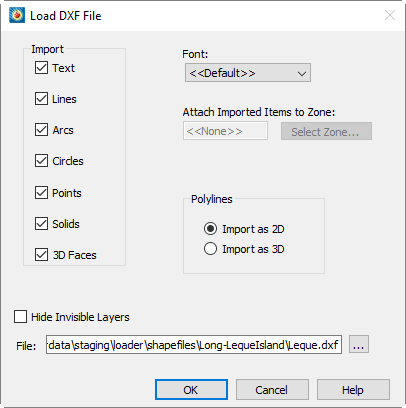
- Import
-
Select any or all geometries to import: Text, Lines, Arcs, Circles, Points, Solids, 3D Faces.
- Font
-
Select the font to use for text. (See Font Folders and Fallback for more information on how fonts work with Tecplot 360.)
- Attach Imported Items to Zone
-
Specify a zone to which all imported geometries will be attached. Clicking the button produces a menu of zone options.
- Polylines/Import as 2D
-
All lines and polylines are stored with three coordinates in DXF files. If you select this option, the loader will add 2D line geometries for all lines and polylines in the DXF file (the third coordinate will be ignored).
- Polylines/Import as 3D
-
If you select this option, the loader will add 3D line geometries for all lines and polylines in the DXF file. To view a 3D DXF file, create or load a 3D zone, import your DXF file, then choose from the menu.
- Hide Invisible Layers
-
If this option is checked, objects in layers that are "off" in the DXF file will be imported with the background color.
DXF Loader Limitations
The DXF Loader does not create any field data. Loading a DXF file only adds geometries to your existing frame.
Since most geometries in Tecplot 360 are 2D, best results will be obtained by loading "flat" DXF files, such as maps.
Binary AutoCAD® DWG™ are not supported in this release.
EnSight Loader
The EnSight Data Loader allows you to load EnSight Gold and EnSight 6 files of types case (.case or .encase), geometry (.geo), or variable (.*). Geometry and variable files can be in either ASCII or binary format, although binary is recommended. Files from earlier versions of EnSight need to be resaved in Gold format using . To determine what format the files are in, view the case file and look under the FORMAT section.
EnSight data is stored in a case file, which contains references to all associated geometry and variable files. Loading the case file will load all the associated files. EnSight parts are translated into zones with the caveat that unstructured parts with dissimilar element types (i.e. a volume element and a surface element) will only load the primary element type. Unstructured zone names will be prefixed by the type of zone they represent (point, line, surface, or volume). Vector, tensor, and tensor9 variables are expanded into the appropriate number of variables with the variable name followed by a suffix. Complex 'imaginary' variables will have an 'I' following the name to distinguish them from the 'real' variable.
When loading Ensight data, choose the desired case file, and the associated data files will be loaded.
Macro Commands for the EnSight Loader
The syntax for loading EnSight data files with the Tecplot macro language is as follows:
$!READDATASET
' "STANDARDSYNTAX" "1.0" "FILENAME_CASEFILE" "file name"'
DATASETREADER = 'EnSight Loader'
Each name/value pair should be in double quotes. Refer to the Scripting Guide for details on working with the Tecplot macro language.
| Keyword | Available Value(s) | Default | Notes |
|---|---|---|---|
STANDARDSYNTAX |
1.0 |
n/a |
Must be the first instruction. |
FILENAME_CASEFILE |
"filename" |
n/a |
The full or relative path of the case file name. |
READDATAOPTION |
NEW, APPEND, REPLACE |
n/a |
NEW to create new layout; APPEND to add to existing layout, REPLACE to replace data and retain style |
Previous versions of the EnSight loader supported options for loading a subset of the data using IJK skipping, part selection, or variable selection. These options will not generate syntax errors, so old macros will continue to work. However, IJK skipping is ignored, and part/variable selection is supported only for Ensight 6 files.
Excel Loader
The Excel Loader can read numeric data from .xls files for Microsoft® Excel® version 5.0 or higher.
| The is available for Windows platforms only. |
The Excel Loader is intended primarily for users who record experimental or simulation data using Excel. Your Excel file must contain only values (no equations). We recommend the use of the Excel add-on from the Util/Excel folder as an easier method to open Excel data with Tecplot 360 (see Excel Add-In). Use the Text Spreadsheet loader for delimited files (Text Spreadsheet Loader).
If your spreadsheet is arranged as Table Format or Carpet Format, the Excel Loader is a point-and-click operation. Once you have selected an Excel file to load, the Excel Loader leads you through a series of dialogs, prompting you to specify a variety of attributes, including the data format in the Excel spreadsheet, the variables to be read, and zone information.
| Refer to Excel Add-In for instructions on loading Excel data into Tecplot 360 from Excel. |
Spreadsheet Data Formats
The Excel Loader will automatically identify blocks of data in
Table Format or Carpet Format. The loader
will list blocks of data in standard notation for Microsoft Excel. For example, a block
found on worksheet sheet1, cells A1-D8, is listed as follows: (sheet1! A1:D8).
If you select a user-defined format (or if the loader did not identify any carpet or table blocks), you will be prompted to enter the names and number of variables, and one or more zones and associated properties. You will also need to enter the location of the field data in the spreadsheet for each zone.
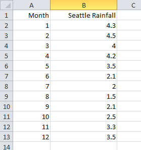
Table Format
Use Table format for data that will be plotted in line plots (i.e. data with an independent and one or more dependent variables). Many spreadsheets containing data to be plotted in 2D or 3D Cartesian plots will also satisfy the conditions of table format.
A table formatted dataset has the following characteristics:
-
The dataset is arranged in one or more adjacent columns.
-
Each column is the same length.
-
Each cell contains numeric data.
-
The first row is a header row containing the variable name for its corresponding column.
-
The spreadsheet dataset is imported as a single I-ordered zone in
POINTformat withNvariables, whereNis the number of columns in the table.
|
The block of data must be surrounded by empty cells, text-filled cells, or table boundaries. The loader will not recognize a block of data as being in table format if any cell adjacent to the block contains a number. The block of data can contain no empty cells. An empty cell will prevent the loader from recognizing the block. You can satisfy this condition by filling blank cells with 0.0. |
Figure 1 shows a block of data in table format in Excel.
Carpet Format
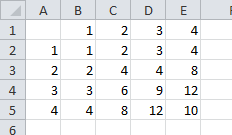
Use carpet format for spreadsheet data to be plotted in a 2D or 3D Cartesian plot. The carpet formatted dataset, shown in Figure 2, has the following characteristics:
-
The spreadsheet dataset is imported as an IJ-ordered zone. See XY and Polar Line Plots.
In Figure 2, the spreadsheet is imported as I=4 and J=4. The three variables are X, Y, and V. In the spreadsheet cell 2B is index
1,1, cell 3B is index2,1. -
The top row in the block contains the values of the X-variable, the first column of the block contains the values of the Y-variable, and the V-values are the interior data. This format is useful if your dataset was generated from a function f, such that f(X, Y) = V.
-
The block is a rectangular arrangement of numeric data in the spreadsheet, with a blank cell in the upper left hand corner.
-
There must be no blank cells within the block of data. An empty cell will prevent the loader from recognizing the block. You can satisfy this condition by filling blank cells with
0.0. -
The block of data must be surrounded by empty cells, text-filled cells, or table boundaries. The loader will not recognize a block of data as being in carpet format if any cell adjacent to the block is filled with a number.
Other Formats
The Other format option gives you a great deal of flexibility in loading data into Tecplot 360. A series of dialogs leads you through the process of describing your data, similar to the way you would specify this information in a Tecplot-format ASCII file.
- Default format
-
The Excel Loader offers a semiautomatic option that requires only that you specify the upper left and lower right corners of your data block. Once you’ve specified those corners, it handles the data in the same way that Tecplot 360 handles an unformatted block in an ASCII file. It assumes one zone of I-ordered data in
POINTformat. - Custom format
-
Using the Custom format option, you can specify characteristics of your dataset. Custom format has the following features:
-
It allows you to work with spreadsheets containing blank cells or text cells.
-
For XY, IJ, and IJK-ordered data, specify the boundaries of the block to load, and how many data points there are within that block (IMax, JMax, KMax).
-
For finite element data, the number of data points is implied by the number of nodes and number of elements.
-
Allows you to load blocks of cells that you delimit interactively.
-
It is the only option for loading finite element, IJK-ordered, or zone data from Excel. If you want to read data from an Excel spreadsheet into more than one zone, you must use custom format. By default, all data read is put into a single I-ordered zone.
-
Excel Loader Restrictions
A block of data is a rectangular group of numbers in the spreadsheet. The Excel Loader places the following restrictions on blocks:
-
Carpet and table format (which the loader detects and loads automatically) are narrowly defined. All other formats must be loaded on the user-defined pathway.
-
Numeric cells within each block should contain only numbers or numeric characters such as
+,-, and so forth. A cell containingX=34is interpreted by the loader as text, because it begins with text. -
Cells containing formulas (therefore displaying calculated values) will be skipped by the loader. You can convert the formulas to values within Excel, by pasting your table using the "Paste Special" function, with "values only" selected.
-
The spreadsheet file must have been written by Excel Version 5.0 or higher. For newer versions of Excel (Office 2007 and later) that save in .xslx format by default, please switch to the older .xsl format when saving your file.
Exodus Loader
The Exodus file format is based on the netCDF file structure created by Sandia National labs. The Exodus library functions provide the mapping between FE data objects and netCDF dimensions, attributes, and variables. The accepted Exodus file extensions are *.e, *.e.*, *.exo, *.exo.*, *.exoII, *.exoII.*, *.g, *.g.*, *.gen and *.gen.*.
Macro Commands for the Exodus Loader
The syntax for loading Exodus data files with the Tecplot macro language is as follows:
$!READDATASET
' "STANDARDSYNTAX" "1.0" "FILENAME_FILE" "filename"'
DATASETREADER = 'Exodus File Loader'
Each name/value pair should be in double quotes. Refer to the Scripting Guide for details on working with the Tecplot macro language.
| Keyword | Available Value(s) | Default | Notes |
|---|---|---|---|
STANDARDSYNTAX |
1.0 |
n/a |
Must be the first instruction. |
FILENAME_FILE |
"filename" |
n/a |
The name of the file to load. |
FILELIST_DATAFILES |
"n" "file-1" "file-2"…. "file-n" |
n/a |
Specify the number of solution files, followed by each file name. |
INCLUDESIDESETS |
"True", "False", "T", "F", "Yes", "No", "Y", "N" |
n/a |
If name value pair is not present, side sets are not included. |
ELEMENTBLOCKGROUPING |
"ElementDimension" or "ElementBlock" |
n/a |
ElementDimension: All element blocks containing elements of the same dimension are grouped together into a single zone (one per time step) and, if transient, strand ID. For instance an Exodus dataset containing one or more Hex8 element blocks and one or more Shell4 element blocks is loaded into Tecplot as an FE-brick zone and a FE-quad zone. Element dimension grouping is the default loader behavior if the name/value command is not present in the loader instructions. ElementBlock: All element blocks are assigned individual zones (one per time step) and, if transient, strand IDs. |
FEA Loader
Tecplot 360 includes the ability to load input and solution files from many popular finite element analysis (FEA) solvers. Supported formats include:
| Solver/File Format | File Name/Extension |
|---|---|
3D Systems STL |
.stl |
ABAQUS Data |
.fil |
ABAQUS Input |
.inp |
ABAQUS Output Database |
.odb |
ANSYS CFX |
.res |
ANSYS Result |
.rst, .rth, .rfl |
LSTC-DYNA Input |
.dyn, .k |
LSTC-DYNA Taurus State |
D3PLOT |
MSC/NASTRAN Bulk Data |
.bdf |
MSC/NASTRAN Output2 |
.op2 |
MSC/PATRAN Neutral |
.out |
OpenFOAM |
controlDict |
PTC/Mechanica Design Study |
.neu |
SDRC/IDEAS Universal |
.unv |
The file formats supported for each solver’s formats are:
| Solver | Version |
|---|---|
3D Systems STL |
all |
ABAQUS |
up to 2024 |
ANSYS |
up to 2022 R1 |
ANSYS CFX |
up to 2024 R2 |
LST-DYNA |
up to 970.0 |
MSC/NASTRAN |
up to 2018 |
OpenFOAM |
2.0, including compressed files |
PTC/Mechanica Wildfire |
up to 4.0 |
SDRC/IDEAS NX |
up to Series 11 |
Format-Specific Notes
ABAQUS Output Database files are supported on Windows only. Other ABAQUS formats are supported on all platforms.
Abaqus .odb files from older versions will be converted to the current format before being loaded through the user interface. However, this conversion will not occur automatically for files loaded with a layout file or via a macro command. To work around this, you will need to convert the older .odb file by loading it explicitly and saving the new .odb file. Then replace the file names in their layouts/macros with the new names using a text editor.
Von Mises stress data is loaded for NASTRAN data files that contain it. The FEA loader also can load both cell-centered and nodal data from NASTRAN files. This ability was added in Tecplot 360 2016 R3 and may cause macros and layouts that refer to variables by number to choose the wrong variable. A warning will appear when loading such files. To address the warning, re-create the layout or macro, or else update the style settings as necessary and change the !$READDATASET instruction in the layout or macro to include the parameter "FEALoaderVersion" "436".
Loading FEA Data
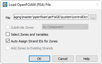
FEA formats have "(FEA)" appended to the format names in the Load Data dialog. Choosing to open a selected file using the FEA loader’s advanced options displays a dialog like the one below. The dialog shown is for the ANSYS Result file format, but all formats use the same dialog (only the file format, displayed in the dialog’s title bar, differs)
-
Click the button to change the file you wish to load. By default, it is the file you selected in the Load Data dialog.
| For OpenFOAM cases, load the controlDict file in the case’s system directory. The OpenFOAM loader currently supports polyhedral and non-polyhedral data including surfaces and boundaries, parallel data, and compressed data. If a file contains transient data, this loader loads all time steps including step 0. |
- Subdividing Zones
-
Each zone loaded from an FEA file typically represents the entire solution at a particular time step or load increment. Sometimes a solution will consist of many components that you may wish to display individually. To activate this option, choose the "Subdivide Zones" toggle and select the desired subdivision option from the menu. Tecplot 360 provides you with two ways to subdivide zones: by Component and by Element Type.
- Subdividing Zones by Component
-
Some FEA file formats include the ability to identify components or sub-regions. If this information is available, you may direct Tecplot 360 to apply it by selecting the "by Component" option. Components within each solution step will be identified by sequentially numbered zone names in Tecplot 360, for example, "Component 1 Step 1 Incr 1," "Component 2 Step 1 Incr 1," and so on.
- Subdividing Zones by Element Type
-
If component information is not available in a solution file, the above option will produce only one component per solution step and increment. In this case, it may still be possible to achieve the desired effect if sub-regions in the solution are represented by different element types, such as shell elements and brick elements. Selecting "by Element Type" from the subdivision option menu creates a separate Tecplot zone for each element type present in the solution file. Tecplot zone names will then represent each element type, for example, "Quadrilaterals Step 1 Incr 1" and "Tetrahedrals Step 1 Incr 1." This makes it easy to operate on individual components or sub-regions in Tecplot 360’s dialog by selecting the desired zones by name.
- Selecting Zones and Variables to Load
- Auto Assign Strand IDs for Zones
-
Regions or components of solutions throughout an unsteady solution are tracked by Strand IDs. All zones that represent a particular region or component are assigned the same Strand ID. Selecting this option directs Tecplot 360 to assign Strand IDs to the loaded zones. This ensures that only the zones representing the chosen solution time are displayed in Tecplot 360. Zones that do not have Strand IDs assigned are displayed at all solution times. See also Time Aware.
- Add Zones to Existing Strands
-
If you are appending data to an existing dataset, select Add Zones to Existing Strands to append the new zones to existing strands. This is appropriate where the new data represents the same regions or components as are represented in the existing dataset, such as an additional solution time level of an unsteady solution.
Selecting Zones and Variables to Load
By default, Tecplot 360 loads all zones and variables present in the solution file, unless multiple steps or increments are present. In this case, Tecplot 360 will not load step 0 increment 0 (which normally has no solution data associated with it). If you wish to load step 0 increment 0, or a subset of the available zones or variables, choose the "Select Zones and Variables" toggle in the main loader dialog. When you then click OK, the dialog will be displayed, as shown below:
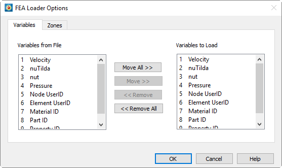
Use the , , , and buttons to add or subtract zones or variables from the list.
The page is displayed above. The page displays the zone list. If you elect to subdivide zones, the zones will be subdivided in the list. The figure below shows a zone list where "Subdivide Zones by Component" has been chosen:
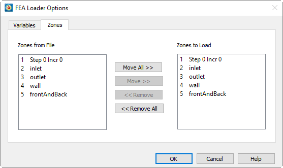
When you have selected the zones and variables you wish to load, select .
The resulting Tecplot zones for each step and increment in the file will be named accordingly in Tecplot 360, beginning with Step 1 Incr 1. The precise meanings of "Step" and "Increment" are solver and problem-dependent, but normally correspond to time steps in unsteady cases, load increments in steady-state cases, or frequencies or vibrational modes in harmonic analyses.
Appending Finite Element Data to an Existing Dataset
If you wish to add a finite element solution to data you have already loaded, select "Add to current data" set in the dialog, which appears after you have selected the file and zones and/or variables to load.
Zones from the file will be added sequentially at the end of the current zone list, and new variables, if any, will be appended to the current variable list. The new zones will not be plotted initially. To plot the appended zones, select them in the dialog, toggle on the checkbox, and choose .
Post-processing Finite Element Data
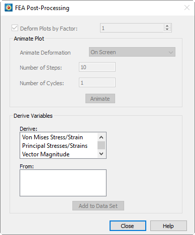
When you load an FEA solution into Tecplot 360, the dialog is displayed if Advanced Options checkbox is turned on in the initial Load Data dialog (unless you are appending to an existing solution). You may re-display it at any time by selecting "FEA Post-processing" from the menu.
|
The following formats will trigger the automatic display of the FEA Post-Processing dialog:
|
The three sections of this dialog allow you to: deform the plot using deformation read from the solution file, animate the deformation, and derive new variables from the solution variables.
- Deforming the FEA Plot
-
Finite element solutions commonly include deformations calculated from applied loads. When a solution is initially read in, the un-deformed geometry is displayed. If the file contains deformation data, you can display the deformed geometry by toggling-on "Deform Plots by Factor". The deformation factor is displayed to the right of this toggle. You may enter the deformation factor in this text field, or use the up or down arrows next to it to change it. By default, the Deform Plot by Factor toggle is checked and the field is set to "1".
- Deriving New Variables from an FEA Solution
-
FEA solutions may consist of various types of stress and strain, or gradients of scalar quantities such as temperature. The lowest section of this dialog allows you to calculate certain other quantities of interest that may be derived from these basic solution variables. For tensor quantities such as stress and strain, the principal stresses or strains plus Von Mises stress are available. For vector quantities, the vector magnitude may be calculated. Choose the derivation you want in the Derive list, and a list of candidate source variables in the solution will be displayed in the From list. Choose the source variable and click to add the desired quantity to the dataset. If Tecplot 360’s Calculate-on-demand feature is active, the variable will only actually be calculated when it is displayed. In this case, you may notice no delay when you select , but some delay later when you choose to display the variable by selecting it, for example, as the contour variable.
Macro Commands for the FEA loader
You may also load FEA data files with the Tecplot macro language. The syntax is as follows:
$!READDATASET
' "STANDARDSYNTAX" "1.0"
"...any of the name value pairs in the following table..." '
DATASETREADER = 'FEA LOADER' See List below
The value for the DATASETREADER parameter should match the name of the loader as shown in the Select Import Format dialog, or as listed below.
-
ANSYS® Results (FEA)
-
ABAQUS Input (FEA)
-
ABAQUS .fil Data (FEA)
-
ABAQUS Output Database (FEA)
-
LSTC/DYNA Input (FEA)
-
LSTC/DYNA Taurus State Database (FEA)
-
MSC/NASTRAN Bulk Data (FEA)
-
MSC/NASTRAN Output2 (FEA)
-
MSC/Patran Neutral (FEA)
-
OpenFOAM (FEA)
-
PTC/Mechanica Design Study (FEA)
-
SDRC/IDEAS Universal (FEA)
-
3D Systems STL (FEA)
Each name/value pair should be in double quotes.
| Keyword | Available Value(s) | Notes |
|---|---|---|
STANDARDSYNTAX |
1.0 |
Required as the first instruction. |
FEALoaderVersion |
"424", "435", "436", "443", "446", "450", "452", "461", "66051", "131842" |
Indicates the version of the loader that recorded the macro. Later versions of the loader emulate older versions where necessary. Current version is "131842". |
Append |
"Yes" or "No" |
Specify whether to append the current dataset with the FEA file(s). |
FILENAME_File |
"filename" |
Specify the full or relative path of the file name. |
SubdivideZonesBy |
"DoNotSubdivide" |
Specify method of zone division. |
AutoAssignStrandIDs |
"Yes" or "No" |
Set to "Yes" to have Tecplot 360 assign the strand IDs. |
AddToExistingStrands |
"Yes" or "No" |
Available only if Append is set to "Yes". |
ZoneList |
"Z1,Z3,Z6-Z8,…" |
Specify the list of zones to load. You may specify a comma-separated list or use a range (-). |
VarNameList |
"VarName1 + VarName2" + … |
Specify the list of variables
to load. Use the |
InitialPlotType |
"Cartesian3D" |
Set the initial plot type. |
ShowFirstZoneOnly |
"Yes" or "No" |
Specify whether to show only the first zone. |
BoundaryZoneConstruction |
"Reconstructed" or "Decomposed" |
Set how the boundary zones are constructed. Available for OpenFOAM datasets only. |
IncludeSolutionDependentVariables |
"Yes" or "No" |
Specifies whether Solution Dependent Variables should be loaded. Available for Abaqus ODB datasets only. Defaults to "No" if omitted. |
Example
The following example loads "myfile.odb" with the Abaqus Output Database loader. Zones 1 & 2 are loaded, along with the following variables: external force, stress, material ID, and part ID.
$!READDATASET
'"STANDARDSYNTAX" "1.0"
"FILENAME_File" "myfile.odb"
"SubdivideZonesBy" "Component"
"AutoAssignStrandIDs" "Yes"
"ZoneList" "1-2"
"VarNameList" "External Force"+"Stress"+"Material ID"+"Part ID"
"InitialPlotType" "Cartesian3D"
"ShowFirstZoneOnly" "No"'
 DATASETREADER = 'ABAQUS Output Database (FEA)'
FLOW-3D Loader
The FLOW-3D loader allows you to load restart and selected FLOW-3D data files into Tecplot 360. This loader supports Flow3D 11.0.1.15.
| When working with FLOW-3D data in Tecplot 360, we recommend linking the solution time between frames using Frame→Frame Linking. |
The dialog has the following options:
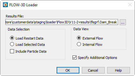
- File
-
Use the browse button to launch the dialog which will allow you to navigate to the data file you would like to load. You may load data files with the flsgrf extension only. Alternatively, you may type the full path of the data file in the File text field.
When loading a parallel (MPI) results file, selecting flsgrf1 loads the data for all files. Selecting flsgrf# will load a single file’s data, where # is an integer greater than 1.
- Data Selection
-
Use the Data Selection region of the dialog to specify whether to load restart or selected data. You may also opt to Include Particle Data or to select a Data Subset.
- Load Restart Data
-
Select this option to load restart data into Tecplot 360. Restart data contains every simulation variable at a small number of time steps.
- Load Selected Data
-
Select this option to load selected data. Selected data typically includes fewer variables than restart data. However, it usually has a larger number of time steps. Selected data is used to output variables of interest at many time steps without bloating the output file with "uninteresting" variables.
Selected data is available in the file only when you request it before the simulation run. - Include Particle Data
-
Toggle-on "Include Particle Data" to load the particle data from your data file.
- Data View
-
Use the Data View region of the dialog to specify whether to view the data as external or internal flow. This option affects how the solid surfaces are drawn at block boundaries. For external flows, surfaces are drawn only at blocked boundaries in the mesh. This option is recommended for solutions that involve flow around obstructions in free space. For internal flows, surfaces are drawn around open space in the mesh, and blocked surfaces are eliminated. This option is recommended for solutions that involve flow into an enclosed volume, such as casting results.
- Specify Additional Options
-
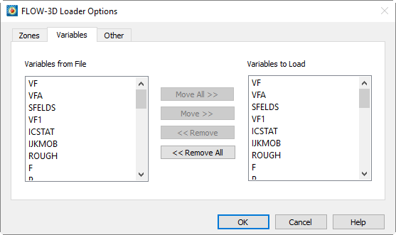
Select the "Specify Additional Options" toggle to launch the FLOW-3D Loader Options dialog after selecting on the dialog. The FLOW-3D Loader Options dialog allows you to load a subset of zones and/or variables from the data file. The Options page of the dialog allows you to specify transient options, specify boundary cell options, and calculate the complement of F.
FLOW-3D Loader Options
The dialog is launched when you select the "Advanced Options" toggle in the initial Load Data dialog.
Zones Page
Use the Zones page of the dialog to select which zones from your dataset to load into Tecplot 360. The box on the left lists the available zones, and the box on the right lists the variables selected to load into Tecplot 360.
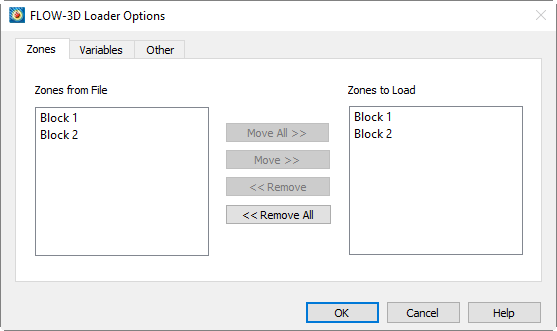
Other Page
Use the Other page of the dialog to specify transient options, boundary options, and whether to calculate the complement of F.
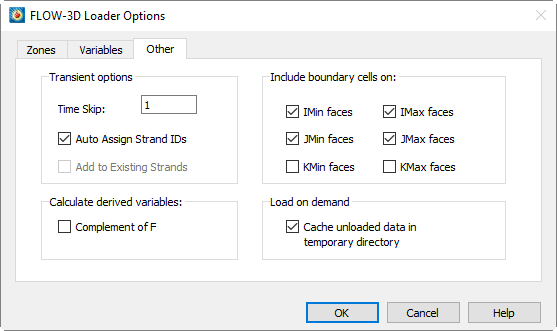
The page has the following options:
- Transient Options
-
Use the Transient Options region of the dialog to specify:
- Time Skip
-
Specify the interval between each loaded time step. A value of one loads all time steps, a value of two loads every other time step, and so forth.
- Auto Assign Strand IDs
-
Select this option to allow Tecplot 360 to assign the Strand IDs to your data. Regions or components of solutions throughout an unsteady solution are tracked by Strand IDs. All zones that represent a particular region or component are assigned the same Strand ID. Selecting this option directs Tecplot 360 to assign Strand IDs to the loaded zones. This ensures that only the zones representing the chosen solution time are displayed in Tecplot 360. Zones that do not have Strand IDs assigned are displayed at all solution times. See also Time Aware.
- Add Zones to Existing Strands
-
If you are appending data to an existing dataset, select Auto Assign Strand IDs to Zones in order for Tecplot 360 to append the new zones to existing strands. This is appropriate where the new data represents the same regions or components as are represented in the existing dataset, such as an additional solution time level of an unsteady solution.
For more information on working with transient data, refer to Time Aware.
- Calculate Derived Variables
-
Use the Calculate Derived Variables region of the dialog to opt to include the Complement of F. The complement of F is calculated as:
where is the fluid fraction and is the volume fraction.
The Fluid Surface, where Fluid Surface , is always calculated and added to the dataset.
- Include Boundary Cells On
-
Use the boundary cell region of the dialog to specify whether to load boundary cells on the I, J, or K extrema. An additional layer of boundary cells will be loaded on the given side of each block for each extremum selected.
- Load on Demand
-
Toggle-on "Cache unloaded data in temporary directory" to enable Tecplot 360 to create a temporary directory to cache the data. The data in the temporary directory is formatted such that it may be quickly read back into Tecplot 360 as needed.
FLOW-3D Macro Commands
The $!READDATASET macro command is extended for the FLOW-3D loader with the following
options:
| Keyword | Values | Default | Notes |
|---|---|---|---|
StandardSyntax |
1.0 |
None |
|
FILENAME_File |
Path to flow-3d results file |
None |
Specifies the path to the file to load. |
DataGroup |
"Selected" or "Restart |
"Restart" |
Specifies which data group to load from the file. |
IncludeParticleData |
"Yes" or "No |
"No" |
" |
DeriveCompOfF |
"Yes" or "No |
"No" |
" |
Append |
"Yes" or "No |
"No" |
" |
AutoAssignStrandIDs |
"Yes" or "No |
"Yes" |
" |
ZoneList |
Set of zone numbers to load from the file. |
All |
FLOW-3D refers to these as "blocks." Really, they are a set of zones that will belong to the same StrandID. |
VarNameList |
Set of variable names to load from the file |
All |
X, Y, Z, and "Fluid Surface" are always loaded |
DataView |
"Internal" or "External" |
External |
Specify whether to view the data as an internal or external flow solution. |
IncludeBoundaryCells |
"YES/NO" |
"Yes" for all entries |
Specify 6 boolean values for including boundary cells. The values are use the following order for the boundary cells: IMIN, IMAX, JMIN, JMAX, KMIN, KMAX |
FLOW-3D Auxiliary Data
The following auxiliary data is added to the dataset by the loader:
| Auxiliary name | Value |
|---|---|
Common.UVar |
Number of variable "U" |
Common.VVar |
Number of variable "V" |
Common.WVar |
Number of variable "W" |
Common.VectorVarsAreVelocity |
TRUE |
Common.PressureVar |
Number of variable "P" |
Common.DensityVar |
Number of variable "RHO" |
Common.TemperatureVar |
Number of variable "TN" |
Common.StagnationEnergyVar |
Number of variable "RHOE" |
Common.TurbulentKineticEnergyVar |
Number of variable "TKE" |
Auxiliary Data can be viewed on the Aux Data Page of the Data Set Information dialog (accessed via the menu).
FLUENT Loader
The FLUENT® Data Loader reads FLUENT Version 5 and newer case (.cas) and data (.dat) files up to and including version 14.0. To load files from earlier versions of FLUENT, you must first import them into FLUENT 5 or newer, then resave them in the newer format.
Particle data may also be loaded from an accompanying XML file. If loading a single .dat/.cas pair, all sections of particle data in an accompanying XML file are loaded. If loading multiple .dat/.cas pairs, one particle section is loaded from the XML file for each .dat/.cas pair loaded. If the XML file is invalid, particle data will be skipped, but the rest of the data will continue to be loaded.
When possible, and assuming the user has the necessary permissions to create new files in the directory containing the FLUENT files, the FLUENT loader creates an index file for each case and data file it loads. These files are stored in a subdirectory called tecplot-derived located in the same directory as the case and data files and are used to load the data faster in future sessions. The FLUENT loader assumes that any files it finds in the tecplot-derived directory relate to the case and data files found in the parent directory. If the FLUENT data files are updated, delete the files in the tecplot-derived directory so that the FLUENT loader will regenerate them. (Be sure all Tecplot 360 sessions using the files are closed first.)
Tecplot 360 does not automatically calculate CFD variables from your existing FLUENT data variables. You may add the variables to your plots by performing calculations via the menu. Refer to CFD Analysis for details.
Additionally, Tecplot 360 does not perform the same wall-boundary calculations that are performed by FLUENT. Instead, the cell-centered data will be extrapolated to the boundary.
See also Time Aware for information on working with transient datasets in Tecplot 360.
The following options are available:
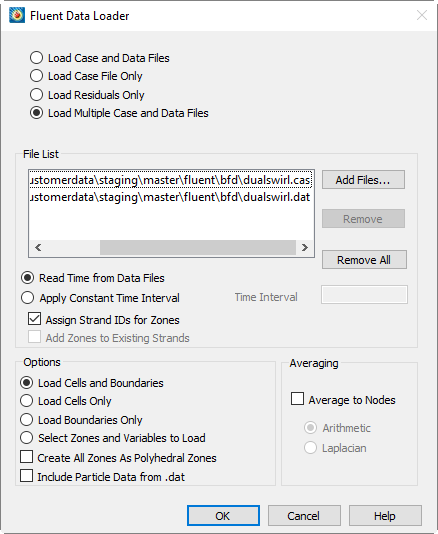
- Load Case and Data Files
-
Loads both a case and a data file. The grid comes from the case file, and the solution comes from the data file.
- Load Case File Only
-
Loads the grid from a case file.
- Load Residuals Only
-
Loads the residual data (convergence history) from a data file. The residuals are not scaled or normalized.
- Load Multiple Case and Data Files (DEFAULT)
-
Displays the File List form in the dialog. You can load matched pairs of case and data files, or one case file and any number of data files that match it (that is, that have the same zones).
For all load options above, except Load Multiple Case and Data Files, the following controls are available:
- Case File
-
Type the name of the case file you wish to load, or click , then select the name of the file from the resulting dialog.
- Data File
-
The data (.dat) file contains the solution and the residual (convergence history) data. Type the name of the data file, or click Select, then select the name of the file from the resulting dialog.
For the Load Multiple Case and Data Files load option, the following controls are available:
- Add Files
-
Choose case and data files to load from a file selection dialog. Selected files are appended to the file list.
- Remove
-
Remove files you have selected in the file list.
- Remove All
-
Remove all files in the file list.
- Flow is Unsteady
-
Indicates that the set of case and data files represents an unsteady solution. The loader adds a TIME auxiliary data item to each loaded zone. Tecplot 360 does not use this data, but other add-ons may.
- Flow Solution is Unsteady/Time Interval
-
The FLUENT data loader saves the problem time of each solution as the solution time variable. There are two options for determining the time to save for each one: (1) reading the flow-time entry from each .dat file, or (2) applying a constant time interval to successive .dat files.
- Read Time from Data Files
-
If this option is selected, Tecplot 360 reads the flow-data parameter from each .dat file. If no .dat files are included (i.e. only .cas files are loaded), the solution time variable will not be created for the zones.
- Apply Constant Time Interval
-
If this option is selected, Tecplot 360 applies the time interval specified in the Time Interval text field to zones created from successive .cas or .dat files. The zones from the first .cas/.dat files are given time 0. Times for successive files are calculated by incrementing the time of the previous files by the specified time interval.
- Assign Strand IDs for Zones
-
Toggle-on to have Tecplot 360 assign Strand IDs to transient zones. Common strand IDs will be assigned to each cell or boundary zone with matching FLUENT zone IDs.
- Add Zones to existing Strands
-
Toggle-on to add the appended zones to StrandIDs in the current dataset.
| Add Zones to existing Strands is available only when the current dataset is being appended and Assign Strand IDs for Zones is toggled-on. |
- Time Interval
-
If "Apply Constant Time Interval" is selected, the time interval entered in the text field is included.
For the load options other than Load Residuals, some or all of the following controls are available:
- Load Cells and Boundaries
-
Loads the cell (solution) and boundary zones from the case file. Each fluid or solid cell zone and each boundary zone will be displayed as a separate zone in Tecplot 360.
- Load Cells Only
-
Loads only the cell (solution) zones. Each zone will be displayed as a separate zone in Tecplot 360.
- Load Boundaries Only
-
Loads only the boundary zones. Each zone will be displayed as a separate zone in Tecplot 360.
- Select Zones and Variables to Load
-
Select in a separate dialog which zones and variables to load. The option requires the loader to pre-scan all files, which can be time-consuming.
- Create All Zones As Polyhedral
-
Select this option to load all FLUENT zones as Tecplot 360 polytope (polygonal or polyhedron) zones. We recommend you select this option, as converting all zones to polyhedral zones eliminates the possibility of hanging nodes and holes in your iso-surfaces or slices. In this case, the number of faces per element is derived from the element-type, and the number of nodes per face is derived from the face-type. The existence of hanging nodes (determined from the existence of a cell-tree and/or face-tree section) adds to the number of faces in the element and the number of nodes in the face that contains the hanging node. Since polygons must have at least 3 nodes, line segment elements will not be converted. When this option is not selected, only FLUENT polytope zones will become Tecplot 360 polytope zones. In this case, if hanging nodes are encountered, Tecplot 360 will create larger faces, compress connectivity, and expand face neighbors.
- Include Particle Data from .dat
-
Some FLUENT simulations include the effects of discrete particles, such as sand grains or water droplets, in the .dat file. Select this option to load this particle data along with the flow solution. All particles from a particular injection will be displayed in a single Tecplot 360 zone (one zone per injection). If you have chosen to select which zones and variables to load, this option is disabled, but the particle zones and variables will be displayed in the selection lists, allowing you to load them with the flow solution.
Newer versions of FLUENT store the particle data in a separate .xml file. To load this data, use the Load Multiple Case and Data Files mode and simply add any .xml files to the file list.
- Average to Nodes
-
Selecting this option directs the loader to average FLUENT’s cell-centered data to the grid nodes. This can speed up subsequent operations in Tecplot 360, especially slicing. FLUENT stores solution data at cell centers (face centers for boundary zones). By default, the FLUENT data loader loads the data cell-centered as well. However, you have the option to average the data to the nodes using Arithmetic or Laplacian averaging. Arithmetic averaging is faster, but calculates values at hanging nodes (nodes in the center of a cell face or edge) only from those cells where the node is a corner. This can lead to discontinuous contours. Laplacian averaging option takes additional neighboring cells into account, and results in smoother contours when hanging nodes are present. By default, non-grid variables are stored at cell centers, consistent with FLUENT.
- Arithmetic
-
A simple, fast arithmetic averaging will be performed.
- Laplacian
-
A more accurate, much slower averaging will be performed that accounts for hanging nodes and cell sizes.
If you chose the Select Zones and Variables to Load option, select only those zones and variables you wish to load from the files dialog.
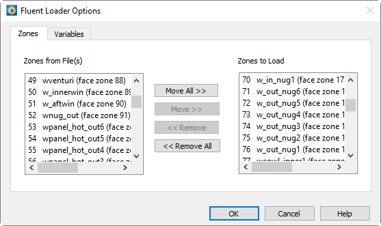
This dialog has a Zones page and a Variables page. The left-hand list of each page shows, respectively, all zones and variables contained in the files you selected. The right-hand list of each page shows the zones and variables that will be loaded when you select . Use the , , , or buttons to edit the Zones/Variables to Load lists.
Macro Commands for the FLUENT loader
The syntax for loading FLUENT data files with the Tecplot macro language is as follows:
$!READDATASET
' "STANDARDSYNTAX" "1.0"
"...any of the name value pairs in the following table..." '
DATASETREADER = 'FLUENT DATA LOADER'
Each name/value pair should be in double quotes. Refer to the Scripting Guide for details on working with the Tecplot macro language.
| Keyword | Available Value(s) | Default | Notes |
|---|---|---|---|
STANDARDSYNTAX |
1.0 |
n/a |
Must be the first instruction. |
Append |
"Yes" |
"No" |
Specify whether to append the current dataset with the FLUENT file(s). |
LoadOption |
"CaseAndData" |
n/a |
Specify whether to load case and data files, a case file only, residual data only, or multiple case and data files. |
FILENAME_CaseFile |
"filename" |
n/a |
Specify the full or relative path of the case file name. Used if the LoadOption is CaseAndData or CaseOnly. |
FILENAME_DataFile |
"filename" |
n/a |
Specify the full or relative path of the data file name. Used if the LoadOption is CaseAndData or ResidualsOnly. |
FILELIST_Files |
"n" "file1" "file2"… "filen" |
n/a |
Specify the number of files, followed by each file name. Only available if the LoadOption is MultipleCaseAndData. |
UnsteadyOption |
"ReadTimeFromDataFiles" |
"ReadTime |
Only available if LoadOption is MultipleCaseAndData. For "ApplyConstantTimeInterval", the TimeInterval parameter is required. |
TimeInterval |
"<double→" |
"1.0" |
Specify the value of the time interval. Only available if the UnsteadyOption is set to ApplyConstantTimeInterval. |
AssignStrandIDs |
"Yes" |
"No" |
Only available if LoadOption is MultipleCaseAndData. |
AddZonesToExisting |
"Yes" |
"No" |
Only applicable when Append is set to "yes". |
GridZones |
"CellsAndBoundaries" |
"CellsAnd |
If "SelectedZones" is specified, either the ZoneList parameter, the VarNameList parameter, or both parameters are required. |
ZoneList |
"Z1,Z2,…Z3-37" |
all zones |
Specify the list of zones to load. You may specify a comma-separated list or use a range (-). This option is only available if GridZones is set to SelectedZones. |
VarNameList |
"V1+V2+V3"+…. |
all variables |
Specify the list of
variables to load. Use the |
IncludeParticleData |
"Yes" |
"No" |
Available only for CaseAndData and MultipleCaseAndData load options. Applies only to particle data in the .dat file, if loading particle data from an XML file, the XML file should simply be included as one of the files to be loaded in FILELIST_Files. |
AllPolyZones |
"Yes" |
"No" |
Not available if the load option is ResidualsOnly. Set to "Yes" to convert all zones to Tecplot polytope zones (polyhedral or polygonal). |
AverageToNodes |
"Yes" |
"Yes" |
Specify whether to average the cell-centered data to the grid nodes. |
AveragingMethod |
"Arithmetic" |
"Arithmetic" |
Specify the averaging method to use. Available only if AverageToNodes is set to "yes". |
LoadAdditional Quantities |
"Yes" |
"No" |
Loads additional quantities, such as residuals, which may be stored in the file. |
Fluent Common Fluid Files (CFF) Loader
The "Fluent Common Fluid Files Loader" is a loader based on ANSYS’s latest, HDF5 file format for its Fluent solver. Loader instructions, following Tecplot’s Standard Syntax, are given to Tecplot’s $!ReadDataset command to control how the case and data files are loaded.
Platform support
- Windows
-
Full support
- Linux
-
Full support.
- Mac
-
The loader is based on a binary library from ANSYS that is not supported on the Mac.
Macro Commands for the Fluent Common Fluid Files loader
The syntax for loading Fluent Common Fluid Files with the Tecplot macro language is as follows:
Note that the StandardSyntax 1.0 name/value pair option must be the very first instruction. All other name/value(s) options can be specified in any order.
$!ReadDataSet
' "Standard Syntax" 1.0
...any of the name value pairs in the following table... '
DataSetReader = "Fluent Common Fluid Files Loader"
Each name/value pair should be in double quotes. Refer to the Scripting Guide for details on working with the Tecplot macro language.
| Keyword | Available Value(s) | Default | Notes |
|---|---|---|---|
STANDARDSYNTAX |
1.0 |
n/a |
Must be the first instruction. |
FileList_DataFiles |
n "file1" "file2"… "filen" |
n/a |
REQUIRED. The FileList_DataFiles command expects an integer count representing the number of files to follow. The count is followed by file paths to one or more case files, where each case file is followed by zero or more data files. Case files must have the extension .cas.h5 and data files must have the extension .dat.h5. |
SolutionTimeSource |
Auto |
Auto |
Auto: Loader first looks for and uses solution time specified in the simulation settings of the Fluent Cff data files. If that information isn’t present in all supplied data files, the loader looks for solution time embedded in the file names. If solution time cannot be determined, the loader assigns strands and a constant time interval, starting at zero and incrementing by one, if there is a single case file, or if there are case and data file combinations, otherwise the loader assigns static stand IDs and a solution time of zero to all zones. SteadyState: Loader assigns static strand IDs and a solution time of zero to all zones. ConstantTimeInterval: Loader assigns strands and a constant time interval, starting at zero and incrementing by one. |
IncludeInteriorFaceZones |
True, Yes, T, Y, |
False |
True, Yes, T, Y: Interior face zones used to build the cell zones are also loaded as independent face zones, and added to the end of the other loaded face zones, such as walls, symmetry, etc. False, No, F, N: Interior face zones are not loaded as independent face zones, however, they are used to construct the cell zones. |
IncludeParticleZones |
True, Yes, T, Y, |
True |
True, Yes, T, Y: If particle data exists in the .dat.h5 file(s) it is loaded and represented as additional I-ordered zones and nodal variables. False, No, F, N: Particle data is not loaded even if it exists in the .dat.h5 file(s). |
Example
$!ReadDataset command using the "Raw String" formatting, which allows the command to
be spread over multiple lines and to contain quotation marks and other characters
without escaping them. Raw strings begin with R"( and end with )" allowing the
string within those delimiters to contain any character that doesn’t match the closing
delimiter:
$!ReadDataset R"(
StandardSyntax 1.0
FileList_Datafiles 6
"/path/to/my/data/vessel-15.cas.h5"
"/path/to/my/data/vessel-15.30001.dat.h5"
"/path/to/my/data/vessel-15.30002.dat.h5"
"/path/to/my/data/vessel-15.30003.dat.h5"
"/path/to/my/data/vessel-15.30004.dat.h5"
"/path/to/my/data/vessel-15.30005.dat.h5"
SolutionTimeSource ConstantTimeInterval
IncludeInteriorFaceZones True
IncludeParticleZones False
)"
DatasetReader = "Fluent Common Fluid Files Loader"
FVCOM Loader
The FVCOM Loader allows you to import netCDF files output from FVCOM into Tecplot 360. Currently, classic netCDF and netCDF-4 formats are supported. The loader imports one or more FVCOM history outputs with the same topology and variable structure into a single Tecplot dataset, creating one zone for each time step. FVCOM history outputs with differing topology or variable structure can be combined but only through appending.
The X and Y grid variables are loaded directly from the file and projected to each Z position, which is derived from the zeta, h and siglev variables. The grid variables are chosen based upon the Coordinate System specified in the FVCOM attribute data. If no Coordinate System is provided, Cartesian is assumed.
The following auxiliary data is added to the data by the loader:
| Auxiliary Name | Cartesian | Spherical |
|---|---|---|
Common.XVar |
Number of variable "x" |
Number of variable "lon" |
Common.YVar |
Number of variable "y" |
Number of variable "lat" |
Common.ZVar |
Number of variable "z" |
Number of variable "z" |
The vertical level and layer variables are added for visualization of FVCOM model layers. FVCOM variables stored at the nodes of each sigma level are loaded as nodal variables and variables stored at the elements for each sigma layer are loaded as cell-centered variables. FVCOM variables stored at the nodes of each sigma layer are interpolated to the volume cell-centers ignoring any FVCOM specified boundary conditions. Variables located at the elements of each sigma level are ignored. Attributes for the file and each variable are loaded into dataset and variable auxiliary data respectively.
General Text Loader
The General Text Loader add-on allows you to read ASCII text data files in a variety of formats. You can specify variable and dataset title information or indicate specific places to read them from in your data file. Instruction settings for reading a type of file can be saved and restored so they do not have to be entered again each time a new file of the same type is loaded.
The following options are available:
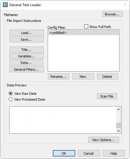
- Filename
-
The name of the file to be loaded. This is automatically filled in with the name of the file selected in the Load Data dialog, but may be changed using the buton.
- Titles
-
Launches the Dataset Title dialog, which allows you to specify dataset title properties.
- Variables
-
Launches the Variable Import Instructions dialog which allows you to specify dataset variable properties.
- Data
-
Launches the General Text Loader: Data dialog which allows you to specify dataset field properties.
- General Filters
-
Launches the General Text Loader: Filters dialog which allows you to specify general filters when reading your file.
- Configuration File List
-
This list shows available configuration files. Configuration files can be edited using a text editor, although this is not usually necessary and is not recommended. The format of these files is listed on the Configuration page.
- Load
-
Loads a single configuration file from any location.
- Save
-
Saves a single configuration file to any location.
- Rename
-
Renames a configuration file.
- Delete
-
Deletes a configuration file.
- New
-
Creates a new, untitled configuration file.
- Data Preview
-
- View Raw Data
-
This displays the data exactly how it looks in the file without any processing.
- View Processed Data
-
This displays the processed and filtered data that will be loaded.
- View Options
-
Launches the General Text Loader: View Options dialog.
Dataset Title
The dialog allows you to specify options for General Text Loader titles.
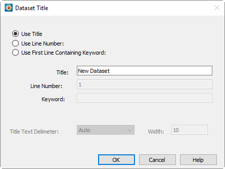
- Use Title
-
Manually enter the dataset title, rather than have General Text Loader scan the file for it.
- Use line number
-
Enter the line number of the dataset title in the file. The General Text Loader skips white space on the line until text, and then reads until the delimiter indicated is found. To include spaces in the title, enclose them in double quotes.
- Use first line containing keyword
-
Enter a keyword for the dataset title line. The title will read the first line containing this keyword (case insensitive). General Text Loader searches for a title on this line in the following order, (unless the delimiter is specified as fixed):
-
First, it will look for any text enclosed in double quotes. If it finds this, then the enclosed text will be read as the title.
-
If no text in double quotes is found, the first non-white space text after the keyword ending with the indicated delimiter will be used.
-
- Text Delimiter
-
The text delimiter indicates when the end of text has been reached. You can set it to one of the following:
- Auto
-
Space, tab, comma, semicolon.
- Fixed
-
Each width number of characters on the line is a token field. White space is removed from the beginning and end of the field.
- Width
-
If the delimiter is fixed, enter the width of each field here.
Variable Import Instructions
The dialog of the General Text Loader allows you to scan for the location of the variable names in the data file, and enter which variables to load.
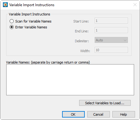
- Scan for variable names
-
Specify the following:
- Start line
-
Enter the starting line of variable names in the file.
- End line
-
Enter the ending line of the variable names in the file. This is typically the same as the starting line.
- Delimiter
-
The delimiter indicates when the end of each variable name has been reached. You can set it to one of the following:
- Auto
-
Space, tab, comma, semicolon.
- Fixed
-
Each 'width=n' number characters on the line is a variable. White space is removed from the beginning and end of the field. For example, if the line length is 60 and the width is ten, the columns 1-10, 11-20, 21-30, and so forth, are variable names. Spaces are removed from the beginning and end of the variable names.
- Width
-
If the delimiter is fixed, enter the width of each field here.
- Enter Variable Names
-
Select this option to enter a list of variable names in the dialog box. Variable names should be separated by carriage returns.
- Select Variables to Load
-
Launches the dialog.
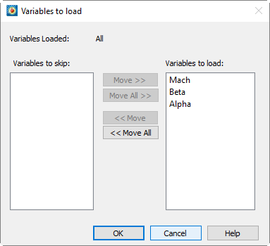
- Variables to Skip
-
Displays a list of variables that will be skipped.
- Variables to Load
-
Displays a list of variables that will be loaded.
Use the , , , or buttons to edit the "Variables to Load" list.
General Text Loader: Data
The dialog of the General Text Loader allows you to specify the location of the data names in the data file, and what data to load.
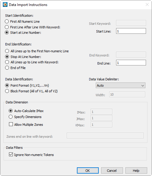
- Start Identification
-
- First all-numeric line
-
Select if the data begins at the first line of a file that contains only numbers. If you have specified multiple zones, all non-numeric lines will be skipped at the beginning of each zone.
- First line after line with keyword
-
Select if the data begins at the first non-blank line after the line containing the specified keyword. The keyword is case insensitive.
- Start at line number
-
Select to specify the line number where the data begins. Blank lines are ignored in the data section.
- End Identification
-
- All lines up to first non-numeric line
-
Select if the data ends at the first non-blank line containing any text.
- Stop at line number
-
Select to specify the line number where the data ends.
- All lines up to line with keyword
-
Select if the data ends at the first line before the line with the specified keyword. The keyword is case insensitive.
- End of file
-
Select if the data ends at the end of file.
- Data Identification
-
- Point format
-
In this format all values of all variables are given for the first point, then the second point, etc.
- Block format
-
In this format all values for the first variable are given, then all values for the second variable, etc.
- Data value delimiter
-
The data value delimiter indicates when the end of a data value has been reached. You can set it to one of the following:
- Auto
-
Space, tab, comma, semicolon.
- Fixed
-
Each 'width=n' number characters on the line is a token field. White space is removed from the beginning and end of the field. For example, if the line length is 60 and the width is ten, the columns 1-10, 11-20, 21-30, and so on, are token fields.
- Width
-
If the delimiter is 'fixed', enter the width of each field here.
- Data Dimension
-
If the data dimensions are entered, General Text Loader adds zones as necessary depending on the number of data points found in the file. There must be an equal number of data points for each zone (equal to the product of the IJK dimensions).
- Auto-Calculate IMAX
-
The I-dimension is calculated based on the number of data points found. J and K-max are set to one.
- Specify Dimensions
-
Specify the I, J, and K-dimensions for the data. There must be enough data points found in the file to match the indicated dimensions.
- Allow Multiple Zones
-
If checked, General Text Loader will attempt to read more than one zone from the data file.
- Zone ends on line with keyword
-
If Allow multiple zones is selected and Auto-calculate IMax is selected, then you must enter a keyword here to mark the end of one zone and the beginning of the next. Zones are ended when a line containing this text is found.
- Ignore non-numeric tokens
-
If checked, then any non-numeric information in the data sections is ignored. If not checked, General Text Loader displays an error if any non-numeric data is found in the data section.
General Text Loader: Filters
Use the dialog of the General Text Loader to filter the data file.
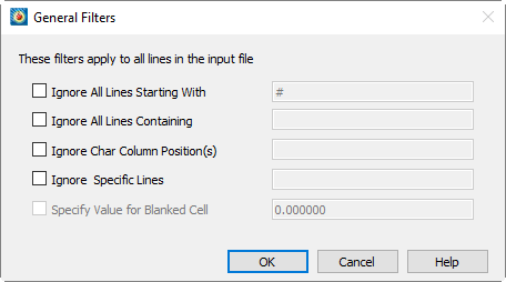
- Ignore All Lines Starting With
-
If checked, all lines beginning with the entered string are ignored.
- Ignore All Lines Containing
-
If checked, all lines containing the indicated text are ignored.
- Ignore Character Column Position(s)
-
If checked, then the entered columns are ignored when scanning the file. Columns are entered as a single number or a hyphenated range, one or more of which may be separated by commas.
If there are tabs in the data file, they are not expanded in this filter. For example, if column 1 is a tab and you wish to skip column 2, you should enter 2, even though a text editor will show more than one space after expanding the tab. - Ignore Specific Lines
-
If checked, entered lines are ignored when scanning the file. Lines are entered as a single number or a hyphenated range, one or more of which may be separated by commas. You may also use "end" to specify the last line of the file.
- Specify Values for Blanked Cell
-
If checked, you can specify a value which the loader uses for blank cells.
This option is only available if the data delimiter is a comma or semicolon. You can change the data value delimiter using the dialog.
General Text Loader: View Options
The dialog of the General Text Loader allows you to specify the data display.
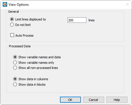
- General Options
-
- Limit lines displayed
-
Limits the number of lines displayed in the preview window. For large files, you may want to set this to a number less than the total number of lines. The fewer number of lines, the faster the preview display.
- Do not limit
-
If you select this toggle, the entire file will be displayed in preview mode.
- Auto Process
-
If selected, General Text Loader automatically refreshes all information about the file whenever any loader settings are changed. For very large files (multi-megabyte), this option is not recommended, since re-scanning a large file can be time consuming.
- Processed Data
-
- Show variable names and data
-
If selected, variable names and processed data will be displayed in the preview window.
- Show variable names only
-
If selected, only variable names will be displayed in the preview window.
- Show all non-processed lines
-
If selected, all lines which will not be loaded will be displayed in the preview window.
- Show data in columns
-
Shows the data in columns where each column is a variable.
- Show data in blocks
-
Shows the data in blocks where each block is a variable.
General Text Loader Configuration File
A configuration file contains all of the instructions that tell the General Text Loader how to load a particular type of text file. This information is collected from the dialog fields and written to a file when you click on the main dialog. The configuration file format is similar to the Tecplot macro language. Configuration files for the general text loader are ASCII text files which use a command set that can describe all loading instructions. Normally you do not need to edit these files, as they are automatically written by the loader when you select New on the main dialog.
| Editing these configuration files by hand is not recommended. |
General Text Loader CONFIGFNAME Command
When reading a dataset using General Text Loader, instead of specifying individual
parameters in $!READDATASET, you may use the CONFIGFNAME command. This consists of:
CONFIGFNAME = <string>
VERSION = <integer>
# version of the template file (default is 100)
# Note: changing the version number may cause unpredictable behavior
TITLE
{
   SEARCH = [NONE|LINE|KEYWORD] # default = NONE
     NAME = <string>
# default = "New Dataset", ignored if SEARCH is not NONE
     LINE = <integer> # 1-based, ignored if SEARCH is not LINE
  KEYWORD = <string> # ignored if SEARCH is not KEYWORD
DELIMITER = [AUTO|TAB|SPACE|SEMICOLON|COMMA|FIXED]
    WIDTH = <integer> # Valid only if DELIMITER = FIXED
}

VARIABLES
{
    SEARCH = [NONE|LINE]
     NAMES = <string> # ignored if SEARCH is SCAN
                       # <string> is a comma separated string
    LOADED = <all|n1,n2,...nn> # list of variables to be loaded
 STARTLINE = <integer> # 1-based, ignored if SEARCH=NONE, default = 1
 {
   STARTID = [FIRSTNUMERICLINE | LINE | KEYWORD]
   {
     KEYWORD = <string> # ignored if STARTID is not KEYWORD

     ENDLINE = <integer> # 1-based, ignored if SEARCH=NONE, default = 1
   DELIMITER = [AUTO|TAB|SPACE|SEMICOLON|COMMA|FIXED]
       WIDTH = <integer> # Valid only if DELIMITER = FIXED
   }
   DATA
   {
     IGNORENONNUMERICTOKENS = <boolean> # default = TRUE
     IMPORT
     LINE = <integer>
     # 1-based, ignored if STARTIDENTIFICATION is not LINE
   }
   ENDID = [FIRSTNONNUMERICLINE | LINE | KEYWORD]
   {
     KEYWORD = <string> # ignored if ENDID is not KEYWORD
        LINE = <integer> # 1-based, ignored if ENDID is not LINE
   }
      FORMAT = [POINT|BLOCK] # default POINT
   DELIMITER = [AUTO|TAB|SPACE|SEMICOLON|COMMA|FIXED]
       WIDTH = <integer> # Valid only if DELIMITER = FIXED
 }

 DIMENSION
 {
    AUTO=<boolean> # default = TRUE
    IMAX=<integer> # ignored if AUTO = TRUE, default = 1
    JMAX=<integer> # ignored if AUTO = TRUE, default = 1
    KMAX=<integer> # ignored if AUTO = TRUE, default = 1
    USEMULTIPLEZONES = <boolean> # ignored if AUTO = TRUE, default false
    KEYWORD=<string> # ignored if USEMULTIPLEZONES = FALSE
 }
}
GLOBALFILTERS # filters are applied cumulatively, so lines matching
# any of the criteria are filtered
{
COMMENT = <string> # ignore lines beginning with <string>
NUMBER = <integer> # ignore all lines starting with line number
<integer>
KEYWORD = <string> # ignore all containing <string> (case insensitive)
COLUMNS = <list> #<list> is a comma separated list of number ranges
# example: "1-80,100-end", etc. Must be in double quotes
ROWS = <list> # same as above
USEBLANKCELLVALUE = <boolean> # if TRUE, then the value of blank cells
is BLANKCELLVALUE
BLANKCELLVALUE = <double> # blank cell value. Ignored if
USEBLANKCELLVALUE is FALSE
}
Where <string> is a file name or file path. Settings will be loaded from the file
name specified in <string>. This command is only allowed in conjunction with the
$!READDATASET command as described below. It may not be used inside a configuration
file.
For example, instead of:
$!READDATASET '"C:\test.txt" "VERSION=100 FILEEXT=\"*.txt\"
FILEDESC=\"general text\" "+""+"TITLE{SEARCH=NONE NAME=\"New
Dataset\" LINE=1 DELIMITER=AUTO WIDTH=10
}"+""+"VARIABLES{"+"SEARCH=LINE LOADED= All STARTLINE=1 ENDLINE=3
DELIMITER=SEMICOLON WIDTH=5
}"+""+"DATA"+"{"+"IGNORENONNUMERICTOKENS=TRUE
IMPORT"+"{"+"STARTID=LINE {"+"LINE=4
}"+""+"ENDID=FIRSTNONNUMERICLINE {"+"LINE=1 }"+""+"FORMAT=IJKPOINT
DELIMITER=AUTO WIDTH=1 }"+""+"DIMENSION"+"{"+"AUTO=TRUE
CREATEMULTIPLEZONES=FALSE
}"+"}"+"GLOBALFILTERS{"+"USEBLANKCELLVALUE=TRUE
BLANKCELLVALUE=0.000000 }"'
DATASETREADER = 'General Text Loader'
Using the CONFIGFNAME command, you can write:
$!READDATASET ' "myfile.dat"
"CONFIGFNAME=c:\config_files\myconfig.lgc" '
# contains all of the instructions in the example above
DATASETREADER='General Text Loader'
Components of the Configuration File
All General Text Loader configuration files must start with the line:
#!TECPLOT_LOADGEN- Instruction Syntax
-
Each instruction file contains commands which describe the loading instructions.
- Comments
-
Any text following
#to the end of the line is ignored. - String Format
-
The
<string>parameter must be enclosed in double quotes. You can include a double quote character in the string by preceding it with a backslash\. For example:-
"This is a normal string"
-
"This is a \"quote\" inside a string"
-
- List Format
-
The <list> parameter type is defined as one or more number ranges, separated by commas, enclosed in double quotes. A number range may be a single number or two numbers separated by a dash. Optionally, you may use "end" to indicate the last valid number. For example:
-
"1"
-
"1,2-7,3"
-
"10-end,3,2-5"
-
- Command List
-
The commands in the file may appear in any order, and any command may be divided into any number of lines (that is, all white space, including carriage returns, is ignored).
HDF Loader
The HDF Loader add-on can load 1D, 2D, and 3D Scientific Data Sets (SDS) from HDF files.[1] When a dataset from an HDF file is imported, the file is scanned and a list of all SDS in the file is displayed in the Scientific Data Sets to load portion of the dialog. Select one or more SDS to import. Every SDS that you select must have the same dimension. A rectangular I, IJ, or IJK-ordered zone (for 1, 2, or 3D data, respectively) is created for each SDS that you select to load.
The dialog has the following options:
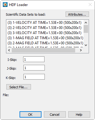
- Scientific Data Sets to load
-
Select one or more SDS’s to load. Each SDS that you select must have the same rank (dimension).
- I-Skip
-
Select the I-Skip value. A skip value of one loads every data point, a skip value of two loads every second data point, and so on.
- J-Skip
-
Select the J-Skip value.
- K-Skip
-
Select the K-Skip value.
- Select File
-
Select an HDF file.
- Attributes
-
Displays attributes of each SDS found, such as number type, rank, label, and so on.
You may also click to choose a different file.
HDF5 Loader
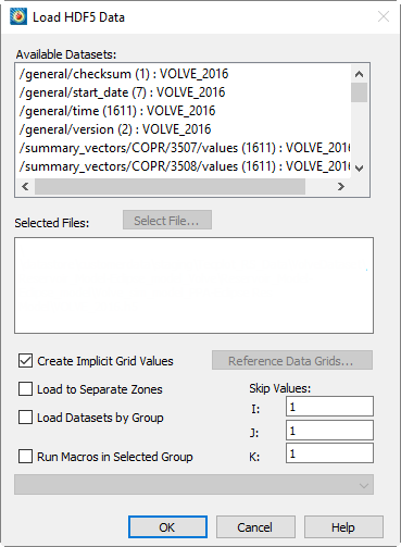
The HDF5 loader add-on allows you to import general HDF5 files into Tecplot 360. The loader provides a mechanism for importing generic data from multiple HDF5 datasets or groups. The HDF5 loader will load datasets within user selected groups, load one or more user selected datasets to one zone, load multiple user selected datasets to multiple zones, execute macros after data has been loaded, create implicit X, Y, and Z grid vectors as needed, sub-sample loaded data, and reference user selected vectors for X, Y, and Z grids. Datasets must be ordered data. The HDF5 library used is version 1.12.0.
Data Selection
One or more files may be opened if all selected files have an identical hierarchy.
Hierarchy information for the selected HDF5 files is displayed in the form:
/group/[group]…/dataset - the dimension of each dataset is displayed immediately
following the dataset name. In this window, one or more datasets or groups may be
selected for loading.
Importing/Loading Data
Datasets may be loaded using one of three methods: 1) Loading Multiple Datasets to One Zone (default), 2) Loading Multiple Datasets to Separate Zones, or 3) Loading Datasets by Group.
Loading Multiple Datasets to One Zone (default)
Loading multiple datasets to one zone is the default method of importing HDF5 files. Using this method, the HDF5 loader will create one zone with N variables, where N is the number of HDF5 datasets selected. Selected datasets may have one to three dimensions. The dimension of loaded Tecplot 360 variables will match the I, J, and K values of the selected datasets. Variable names are assigned the corresponding names of selected datasets. All selected datasets must have equivalent dimensions.
To import your data, select one or more datasets from the window. All selected datasets must be identical in dimension; dataset dimensions are shown immediately to the right of dataset names in the window.
Loading Multiple Datasets to Separate Zones
Using this method, the HDF5 loader will create N zones, where N is the number of datasets selected in the window. Each zone contains one variable per selected dataset where each dataset must have one to three dimensions. The I, J, and K values of each Tecplot 360 zone will match the dimensionality of each selected dataset. Variable and zone names are automatically assigned. Dimensionality may vary between selected datasets.
To import your data using this method, select the "Load to Separate Zones" toggle. Select one or more datasets from the window. One zone will be created for each selected dataset and each zone will contain exactly one variable (unless you selected Create Implicit Grid Values or Reference Data Grids).
Loading Datasets by Group
Using this method, the HDF5 loader will create N zones with M variables, where N is the number of groups selected in the window and M is the number of datasets in each group. The I, J, and K indices of the Tecplot 360 variables will be equivalent to the respective dimension of selected datasets. Datasets in any selected group must be equal in dimension; however, datasets may be unequal in dimension between groups. When selecting multiple groups, all groups must contain an equal number of datasets and dataset names must be identical between groups. The HDF5 loader will only load datasets within the root directory or within a subgroup, i.e., the HDF5 loader will not load data within nested groups.
To import your data using this method, select the "Load Datasets by Group" toggle. Press to open a HDF5 file. Select one or more groups from the window; all groups must contain an equal number of datasets where all datasets have identical names between groups. The number of selected groups determines the number of zones that load into Tecplot 360. Zone names will match the name of the corresponding group. Variable names will match the respective dataset name. Each zone will include as many variables as datasets per selected groups.
Additional Options
Additional options may be specified when loading HDF5 data into Tecplot 360. These options include: Using Macros, Sub-Sampling Data, Referencing Data Grids, and Grid Generation.
Using Macros
Macros may be defined within a HDF5 vector and placed in any group. Each character string in the selected vector must be a valid one-line Tecplot macro. Macros are executed in the order encountered after all data are loaded.
To run a macro defined as a character vector in your HDF5 file, select the "Run Macros in Selected Group" toggle. Select the macro you want to execute from the pull-down menu. Your macro will run after your data has been successfully loaded into Tecplot 360.
Sub-Sampling Data
The HDF5 loader will sub-sample the first, second, and third dimensions of loaded datasets respectively as defined by the user. The default skip-value is 1. When specifying non-unitary skip values, the dimensionality of all selected datasets must be equivalent. Datasets will be sub-sampled using the user defined I-Skip, J-Skip, and/or K-Skip values – skip values must be whole numbers.
To sub-sample data in the first, and/or second, and/or third dimensions of selected datasets, change the respective I-Skip, and/or J-Skip, and/or K-Skip values located in the dialog. If the skip-values are non-unitary then selected datasets must have equivalent dimensions.
Referencing Data Grids
The HDF5 loader allows users to specify X, and/or Y, and/or Z grid vectors. Selected vectors are used for plotting all zones. Vectors are of dimension 1 and length M. The X grid vector length must be equal to the first dimension of selected datasets, the Y grid vector length must be equal to the second dimension of selected datasets, and the Z grid vector length must be equal to the third dimension of selected datasets. The number of selected grid vectors must equal the rank of selected datasets.
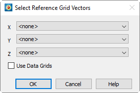
To define the grid vectors, first toggle off "Create Implicit Grid Values" option, then click the button. In the Select Refernce Grid Vectors dialog that appears, select the vector you want to use as the corresponding grid using the menus. You MUST toggle on "Use Data Grids". The number of grid vectors you specify must equal the rank of selected datasets.
Grid Generation
The HDF5 loader can automatically create X, Y, and Z grid vectors as necessary for selected datasets. Grid vectors will be of length equal to the corresponding dimension.
To automatically create X, Y, and Z grid vectors, accept the default setting of "Create Implicit Grid Values" in the dialog. The grid vectors will be created upon loading your data into Tecplot 360.
Kiva Loader
The Kiva loader imports GMV format files that were exported from Kiva.
- Select Input Files
-
From this button, multiple files can be selected in the dialog. Those that are in GMV format will be added to the list of Kiva/GMV files. Once files are added to this list, they will remain in the list throughout the Tecplot 360 session, unless the button is selected.
- File Selections
-
Use the File Selection options for long file lists. Identify the first file to load by entering a number in the Start field, and the last file to load by entering a number in the Stop field.
Enter a value of 2 in the Skip field to load every other file, or 3 or greater to skip more files. To see the list selections updated according to the values in the Start, Stop, and Skip fields, click the button. At any time, you can choose to Select All or Deselect All files.
- Velocity Vector
-
Identify the naming convention for your velocity vectors.
- Loading Options
-
- IsDouble
-
Allows greater precision for your data values.
- LoadParticleData
-
Adds a zone for any files containing particle data.
PLOT3D Loader
The PLOT3D Loader add-on can import data files formatted in PLOT3D format, developed by Pieter Buning at the NASA Ames Research Center.
File Combinations
Use the File Selection page of the dialog to specify whether to load just grid files, both the grid and solution files, or just solution files. When loading grid and solution files together, either one grid file must be loaded (in which case it is assumed that all solution files use this grid), or a number of grid files equal to the number of solution files must be loaded (in which case it is assumed that there is a grid file for each solution file). If multiple grid files are loaded, all must use the same organization (binary or ASCII, etc.). Only the first file is scanned for organization.
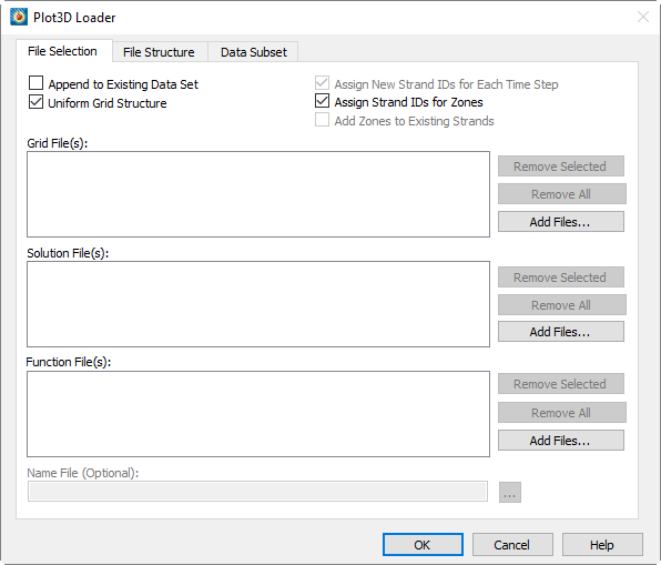
Choosing both solution (or function) and grid files will allow you to optionally specify a name file as well. The name file contains names to replace either the solution or function variable names on a 1-to-1 basis for as many names as are in either file.
If a boundary file exists, it must have a name of the form "gridfilenamewithextension.fvbnd" and be in FieldView 1.4 format to be automatically loaded.
You may append the files being loaded to the current data set by toggling-on the Append option. The files being appended should have the same number of zones as data that has already been loaded. If some zones are static and some are transient, load the static zones and then append the transient zones.
If you are loading more than one grid file and they all have the same structure, make sure the Uniform Grid Structure option is toggled-on for best performance. If you are unsure, toggle-off this option to make sure that the data can be loaded without errors.
This page also allows you to automatically assign Strand IDs for transient zones. An option to add zones to current strands can be used if you are appending additional time steps to existing transient data. Finally, you can have new strand IDs generated for each time step if you want to manage the style of each time step’s data independently.
The Plot3D loader attempts to use numbers in filenames as solution times for transient data. Both integers and decimal fractional values are detected in filenames, and values may be negative. If multiple numeric fields are found in the data set’s filenames, the one with a unique value in each filename being loaded is taken as the solution time; if multiple such fields are found, the rightmost one is used.
| Some solvers that write data in PLOT3D format use the same solution time for all time steps. To accommodate such solvers, the PLOT3D loader will attempt to extract solution times from filenames whenever the solution time information contained in the actual data set is inconsistent or contradictory, even if the loader has not been explicitly instructed to do so. |
The following table describes what the PLOT3D loader does in all six grid/solution scenarios:
| Load | Not Appending | Appending |
|---|---|---|
Grid Only |
Existing dataset is deleted and zones (one per grid) are loaded. |
New zones are added (one per grid). Solution variables in new zones are zeroed out. |
Grid and Solution |
Existing dataset is deleted and zones (one for each grid in each solution file) are loaded. Each set of zones loaded shares spatial variables with the first set of grids loaded. |
Same as "Not Appending" except original dataset is preserved. Existing dataset must have at least as many variables as the number needed by the incoming data. |
Solution Only |
A dataset must already be present. The existing dataset is reduced to contain the same number of zones as there are grids in each incoming solution file. Solution variables in the first solution file replace the solution variables in the original zones. Subsequent solution files create new sets of zones with spatial variables shared with the first set of zones. |
Same as "Not Appending" except original dataset is preserved. Existing dataset must have at least as many variables as the number contained in incoming solution file. Spatial variables are shared with last n original zones where n is the number of grids in each incoming solution file. |
  When loaded from the user interface, the loader attempts to extract solution times
from the filenames. If the function filenames have embedded numeric values that can be
interpreted as solution times, the function files will be treated as if they are
solution files, otherwise the variables in the specified function files are added to
the zones defined in the previously loaded solution files. When loaded from a macro,
this same treatment of function files is achieved by adding the
"EXTRACTTIMEFROMSOLFILENAMES" "YES" name/value pair to the loader instructions given to
the $!ReadDataSet command.
PLOT3D File Structure
The File Structure page of the dialog allows you to choose to have the PLOT3D Loader auto detect the file structure, or override and manually describe the structure.
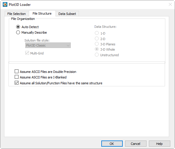
The PLOT3D Loader can automatically detect most PLOT3D file variants. ASCII files are the most difficult to auto-detect as there are a few combinations that have the exact same signature. Pure binary files also have some combinations that have the same signature. You may also specify the file format manually.
To enhance performance when loading multiple solution/function files, the primary solution/function file can be chosen to represent the structure of all subsequent files. To activate this option, toggle-on "Assume all Solution/Function Files have the same structure". You must determine if this is appropriate.
Special File Conditions
Unstructured Data Files
The following ASCII file conditions require special attention:
| Condition | Notes |
|---|---|
Double Precision |
You must tell the loader if the incoming file is single or double precision. |
I-Blanking |
You must tell the loader if the incoming file contains I-blanking. |
3D Planar |
There are some cases where these files can appear exactly the same if they are 3D Whole. The PLOT3D loader always favors 3D Whole. If you need to load 3D Planar in 3D Planar ASCII files you must specify the data structure manually. |
Pure Binary Files
The following pure binary files (binary files without record markers) require special attention:
| Condition | Notes |
|---|---|
3D Planar |
There are some cases where these files can appear exactly the same if they are 3D Whole. The PLOT3D loader always favors 3D Whole. If you need to load in 3D Planar pure binary files you must specify the data structure manually. |
PLOT3D Data Subsets
The Data Subset page of the PLOT3D Loader allows you to: read subsets of ordered zones within the files, specify the desired beginning and ending index values to read, and enter a skip value for each index direction. A skip value of one results in every value in the specified index range being read. A skip of 2 reads every second value, and so on.
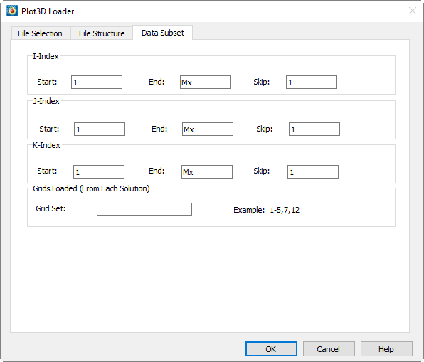
Macro Language Commands for the Plot3D Loader
The syntax for loading PLOT3D data files with the Tecplot macro language is as follows:
$!READDATASET
' "STANDARDSYNTAX" "1.0"
"...any of the name value pairs in the following table..." '
DATASETREADER = 'PLOT3D Loader'
Each name/value pair should be in double quotes:
| Keyword | Value(s) | Default | Notes |
|---|---|---|---|
STANDARDSYNTAX |
1.0 |
n/a |
Must be the first instruction. |
FILELIST_FUNCTIONFILES |
"n" "file-1" "file-2"…. "file-n" |
n/a |
Specify the number of function files, followed by each file name. |
FILELIST_SOLUTIONFILES |
"n" "file-1" "file-2"…. "file-n" |
n/a |
Specify the number of solution files, followed by each file name. |
FILELIST_GRIDFILES |
"n" "file-1" "file-2"…. "file-n" |
n/a |
Specify the number of grid files, followed by each file name. |
FILENAME_NAMEFILE |
"filename" |
n/a |
The associated name file. |
IINDEXRANGE |
"Min, Max, Skip" |
all |
The index ranges for the data to be loaded, minimum, maximum, and skip value. |
JINDEXRANGE |
"Min, Max, Skip" |
all |
|
KINDEXRANGE |
"Min, Max, Skip" |
all |
|
APPEND |
"Yes" or "No" |
"No" |
Whether to append the read data to the existing dataset. |
ASCIIISDOUBLE |
"Yes" or "No" |
"No" |
Whether the ASCII data format is double. |
ASCIIHASIBLANK |
"Yes" or "No" |
"No" |
Whether the ASCII file contains blanks. |
AUTODETECT |
"Yes" or "No" |
Whether to autodetect the PLOT3D file format variant. If set to "No," the DATASTRUCTURE, ISMULTIGRID, and STYLE keywords are used to specify the file format. |
|
DATASTRUCTURE |
"1D", "2D", "3DP", "3DW", or "UNSTRUCTURED" |
none |
Required if |
ISMULTIGRID |
"Yes" or "No" |
none |
Required if |
STYLE |
"PLOT3DCLASSIC" or "PLOT3DFUNCTION" or "OVERFLOW" or "SWIFT" |
none |
Required if |
ASSIGNSTRANDIDS |
"Yes" or "No" |
"No" |
Whether to automatically assign strand IDs. |
ADDTOEXISTINGSTRANDS |
"Yes" or "No" |
"No" |
Whether to add data to existing strands. |
UNIFORMGRIDSTRUCTURE |
"Yes" or "No" |
"Yes" |
Whether the grid structure is the same for all time steps. |
SOLUTIONSSHARESTRUCTURE |
"Yes" or "No" |
"No" |
When loading multiple files whether the primary solution file represents the structure of all subsequent files. Will improve performance. |
EXTRACTTIMEFROMSOLFILENAMES |
"Yes" or "No" |
"No" |
If set to YES for a grid file and one or more solution files or one or more function files without solution files, and the solution or function filenames have embedded numeric values that can be interpreted as solution times, the loader extracts the embedded solution time from the filenames for use as the solution times. Additionally, function files are treated as transient data instead of adding the function file variables to the existing zones. For solution files only, if the option is set to NO, or not part of the loader command, then auto extraction takes place, detecting if there are duplicated solution times, and if duplicates are found, extracting the solution time from the filenames. For function files only, if the option is set to NO, not part of the loader command, or the solution times could not be extracted from the filenames, the function files are not treated as transient data and the variables are added to the existing zones. |
PLOT3D Auxiliary Data
The following auxiliary data is created by the PLOT3D Loader:
| Auxiliary Name | Assigned To |
|---|---|
Common.ReferenceMachNumber |
Dataset and Individual Zones[2] |
Common.AngleOfAttack |
Dataset and Individual Zones[2] |
Common.ReynoldsNumber |
Dataset and Individual Zones[2] |
Common.IsBoundaryZone |
Individual Zones |
Common.BoundaryCondition |
Individual Zones |
Common.DensityVar |
Dataset |
Common.UVar |
Dataset |
Common.VVar |
Dataset |
Common.WVar |
Dataset |
Common.StagnationEnergyVar |
Dataset |
Common.GammaVar |
Dataset |
Common.TurbulentKineticEnergyVar |
Dataset |
Common.TurbulentDissipationRateVar |
Dataset |
Common.VectorVarsAreVelocity |
Dataset |
Common.SpeedOfSound |
Dataset |
G[3] |
Individual Zones |
B[3] |
Individual Zones |
T[3] |
Individual Zones |
I[3] |
Individual Zones |
H [3] |
Individual Zones |
H1[3] |
Individual Zones |
H2[3] |
Individual Zones |
PLY Loader
Use this loader[4] to load 3D triangular surface files with the .ply extension. This format is often used to store surfaces generated from tessellation of 3D range measurement data. Files may be either ASCII or binary, but must contain both vertex and face elements (sections). This loader is included in your Tecplot 360 installation.
PVD Loader
The PVD Data Loader loads VTK (Visualization Toolkit) files which have the filename extension .pvd. The PVD format is essentially a header file that collects together other VTK XML-based data files, such as VTI, VTP, VTR, VTS, VTU, etc.
Opening a single PVD file loads all supported files embedded within it. All zones created from a PVD file will be assigned the same strand ID.
The PVD loader does not have the advanced options dialog but supports advanced options via
the macro language by augmenting the PVD Data Loader instructions in the $!READDATASET
command of a layout or macro file. Multiple PVD files can loaded at once.
The PVD Data Loader will read the <FieldData> section of the files and add any scalars
it finds to the zone’s auxiliary data. The loader can be instructed to use time scalar
values for zone solution times if all of the files have a scalar named "time" or
"timevalue". The PVD loader can optionally detect a consistent pattern of incrementing
numeric values in the names of the files themselves and use them for the zone’s solution
time. If the loader cannot follow the instruction it is given, because not all of the
files have the "time" scalar or because there is no consistent pattern of values in the
filenames, it will not assign a solution time or strand ID.
To tell the loader how to assign solution times, add the name/value pair
SOLUTIONTIMESOURCE <setting> to the loader instructions. The settings are listed
below.
Macro Language Commands for the PVD Data Loader
The syntax for loading PVD data files with the Tecplot macro language is through the
$READDATASET command as follows:
$!READDATASET
' "STANDARDSYNTAX" "1.0" "...one or more PVD Data Loader instructions..."'
DATASETREADER = 'PVD Data Loader'
The PVD DATA Loader instructions are in name/value pairs and each name/value pair should be independently surrounded by double quotes. Refer to the Scripting Guide for details on working with the Tecplot macro language.:
| Keyword | Value(s) | Default | Notes |
|---|---|---|---|
STANDARDSYNTAX |
"1.0" |
n/a |
Must be the first instruction. |
FILENAME_FILE |
"filename" |
n/a |
Specify a single file name. |
FILELIST_DATAFILES |
"n" "file-1" "file-2"…. "file-n" |
n/a |
Specify the number of solution files, followed by each file name. |
SOLUTIONTIMESOURCE |
"FromFieldData", "FromFilename", "Auto", "None" |
"Auto" |
"Auto": Favors the "time" scalar for the solution time over the numbers embedded in file names, "None": Does not assign solution time or Strand ID, "FromFieldData": Uses the "time" scalar for solution time, "FromFileName": Uses the solution time embedded in the file names. |
Tecplot Data Loader
This section describes the process for loading Tecplot-format data files with the extensions .dat for ASCII files and .plt for binary files. Some other products that write Tecplot binary files use the filename extension .bin or .tec, and these are also recognized by the Tecplot-Format loader. (Refer to the Data Format Guide for information on outputting data into Tecplot 360 file format.)
There are four ways to create and work with Tecplot-format data files:
- Generate a Tecplot-format ASCII data file
-
Read the file into Tecplot 360 and work without conversion. If the dataset is altered, save it as an ASCII data file. This method works well for smaller datasets where the convenience of an ASCII file outweighs any inefficiencies.
- Generate a Tecplot-format ASCII data file and convert it to a binary file with Tecplot 360
-
Read it into Tecplot 360, then save it as a binary data file, then work with the binary file. Once you have saved a binary version, you can delete the ASCII version. This works well for large datasets where ASCII inefficiencies are noticeable. See Data File Writing.
- Generate a Tecplot-format ASCII data file, then convert it to a binary file with Preplot
-
Preplot, a utility program included with Tecplot 360, converts ASCII to binary Tecplot-format data files. Once the binary file is created, delete the ASCII version to save space. This works well for identifying problems with data files, since Preplot’s error messages include precise details. This method also works well in batch processing, or if the ASCII data files are generated on another machine. (See the Data Format Guide for a description of Preplot.)
- Generate a Tecplot-format binary data file
-
Read the binary data file into Tecplot 360 and work without conversion. You must use routines provided by Tecplot as part of the TecIO library to write Tecplot-format binary files from C or FORTRAN programs. (See the Data Format Guide for complete details.)
See also Tecplot Subzone Loader for information on loading the newer subzone file format (.szplt), which is optimized for working interactively with larger files. It is straightforward for developers to upgrade software that writes Tecplot binary files using the TecIO library to write subzone files.
Tecplot Data File Loading
The Tecplot Data Loader (accessed via ) allows you to load ASCII (.dat) and binary (.plt) Tecplot-format data files. For both kinds of files, Tecplot 360 supports full data files, grid files, and solution files, where the file types are defined as follows:
- Full
-
Full files contain both grid and solution data. Data files produced for Tecplot products versioned 2006 and earlier are treated as full data files. Full files can be loaded in any order.
- Grid
-
Grid files contain static data for all zones. They have at least one variable or FE connectivity; they may contain both variables and connectivity simultaneously.
- Solution
-
Solution files contain time-varying data for all zones in the file.
You may load more than one Tecplot format file at a time by selecting multiple files in the Load Data dialog. In fact, this is required when loading solution data because the corresponding grid file must be loaded at the same time.
Loading Grid and Solution Data Files
When you are loading grid and/or solution files, please keep the following in mind:
-
Each solution file must be read in after the grid file it is associated with has been loaded.
-
If you load multiple grid and solution files into Tecplot 360, the order the files are listed will be used to determine which grid is used for which solution file(s). For example, if you load a set of grid and solution files in the following order:
-
Grid A
-
Solution A
-
Solution B
-
Solution C
-
Grid B
-
Solution D
-
Grid A will be shared for Solution Files A, B, and C. Grid B will be used for Solution File D.
| You may select multiple files to load by holding the Shift key. However, the order is not always preserved with this method. We strongly recommend that you use the button when loading grid and solution data to make sure the files are added in the order you require. |
-
You may load a grid file with variables or variables and connectivity without loading a solution file. However, you may not load a grid file that contains only FE connectivity data.
Tecplot Subzone Loader
The Subzone Loader (SZL or "Sizzle") allows you to visualize large data files on typical engineering workstations by loading only the data required for a particular operation. Unlike the previous load-on-demand capability, Subzone Load can load partial zones instead of entire zones. This capability requires a new file format, .szplt, which can be loaded using the Tecplot Subzone Loader.
Data can be converted to the .szplt format manually, by loading it into Tecplot 360 and then writing it in SZL format (see Data File Writing). For information on batch-converting files to SZL format, see Batch Converting to SZL Format.
The Tecplot Subzone Loader is used for loading .szplt files stored on your local disk or on a standard network share (that is, a share that is supported by your computer’s operating system). To load files from a Linux remote host on which Tecplot SZL Server is installed, see Loading Remote Data using Tecplot SZL Server.
Macro Commands for the Tecplot Subzone Loader
The syntax for loading Tecplot Subzone data files with the Tecplot macro language is as follows:
$!READDATASET
' "STANDARDSYNTAX" "1.0"
"...any of the name value pairs in the following table..." '
DATASETREADER = 'Tecplot Subzone Data Loader'
Each name/value pair should be in double quotes. Refer to the Scripting Guide for details on working with the Tecplot macro language.
| Keyword | Available Value(s) | Default | Notes |
|---|---|---|---|
STANDARDSYNTAX |
"1.0" |
n/a |
Must be the first instruction. |
FILENAME_FILE |
"filename" |
n/a |
Specify a single file name. |
FILELIST_DATAFILES |
"n" "file-1" "file-2"…. "file-n" |
n/a |
Specify the number of files, followed by each file name. |
Tecplot Layout Loader
The Tecplot Layout loader is used for loading Tecplot layouts (.lay) and layout packages (.lpk). Layouts include only links to the original data files; layout packages include the subset of data needed to view the layout. See Layout Files, Layout Package Files, Stylesheets for more details on creating these files.
Usually it is most convenient to load these kinds of files using the Welcome screen, the or commands, or double-clicking the file in your file manager (e.g. Windows Explorer). However, you can also load layouts and layout packages by choosing and selecting this loader in the Load Data dialog.
This loader has no options; simply choose the desired .lay or .lpk file, and it will be opened.
Telemac Loader
The Telemac Data Loader reads Telemac SERAFIN- and SERAFIND-formatted (.slf, .srf,
.sel or .res) and boundary (.cli or .conlim) files. You may select multiple SERAFIN
and SERAFIND files, but only a single boundary file for a single load.
To load a boundary file, you must either load it along with one or more SERAFIN[D]
files, or else append it to an existing Telemac data set. It does not include its own X
or Y variables, but rather contains references to node numbers in a corresponding
SERAFIN[D] file. It is loaded as a single I-ordered zone. If loaded along with one or
more SERAFIN[D] files, the boundary zone’s X and Y values will be extracted from the
first zone of the first SERAFIN[D] file. If appended to existing data, the boundary
zone’s X and Y values will be extracted from the first zone of the data set.
Telemac solution (SERAFIN) files may be successfully interactively loaded with the
Telemac loader even if the file suffix (.slf, .srf, .sel or .res) has been stripped
off. However, boundary files must have extension (.cli or .conlim) in order to load.
SERAFIN[D] files contain variable names, which are used for the resulting data set
variables. Boundary files contain no variable names, and add the following variables
(unless noted below, refer to Telemac documentation for their meaning):
- BC-h
-
The boundary condition code for depth (LIHBOR)
- BC-u
-
The boundary condition code for u (LIUBOR)
- BC-v
-
The boundary condition code for v (LIVBOR)
- BC-Qs
-
The boundary condition code for tracer (LITBOR)
- BC-open
-
Indicator for closed or open boundary-0 for closed, 1 for open.
Macro Commands for the Telemac Data Loader
The syntax for loading Telemac data files with the Tecplot macro language is through
the $READDATASET command as follows:
$!READDATASET
' "STANDARDSYNTAX" "1.0" "...one or more Telemac Data Loader
instructions..."'
DATASETREADER = 'Telemac Data Loader'| Keyword | Value(s) | Default | Notes |
|---|---|---|---|
STANDARDSYNTAX |
"1.0" |
n/a |
Must be the first instruction. |
FILELIST_TELEMAC |
"n" "file-1" "file-2"…. "file-n" |
None |
Specify the
number of Telemac |
FILENAME_BOUNDARY |
"filename" |
None |
Specify a boundary file to load.
Must either be appened to existing Telemac data or loaded along with one
or more |
Text Spreadsheet Loader
The Text Spreadsheet Loader add-on allows you import simple data from ASCII files. Select the delimiter and I-skip (if necessary) from the dialog.
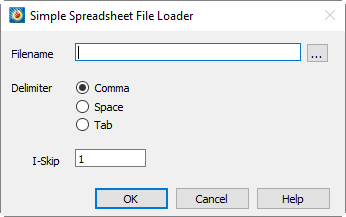
the dialog has the following options:
- Filename
-
Enter the path to the file you would like to load.
- Delimiter
-
Choose whether your data is separated by a comma, space, or tab.
- I-Skip
-
Select an I-skip value. A value of 1 loads all values, a value of 2 loads every other value, and so on.
The Text Spreadsheet Loader can read ASCII files of the following format (blank lines are ignored):
Variable 1, Variable 2, ..., Variable N
datapoint1,datapoint2, ..., datapoint N
.
.
.
datapoint1,datapoint2, ..., datapointN
Here is an example of a valid ASCII spreadsheet file:
Month, Rainfall
1, 15.0
2, 21.0
3, 21.0
4, 32.0
5, 10.3
6, 5.1
7, 2.3
8, 0.2
9, 1.4
10, 8.3
11, 12.2
12, 15.4|
Text Spreadsheet Loader Limitation The first line must contain all of the variable names. See How to Create a Plot |
TRIX Loader
The TRIX Data Loader loads TRIX files, which have the filename extension .trix. TRIX is an XML-based unstructured file format used by Cart3D and related solvers and is a subset of the Visualization Toolkit VTU format. Only triangle surface data can be loaded. The TRIX loader has no advanced options and can load only one file at a time.
VTI Loader
The VTI Data Loader loads structured data VTK (Visualization Toolkit) files which have the filename extension .vti. The VTI format is an XML-based format representing a topologically and geometrically regular data. Examples include volumes (voxel data) and pixmaps. The representation supports images up to three dimensions.
The VTI loader does not have the advanced options dialog but supports advanced options via
the macro language by augmenting the VTI Data Loader instructions in the $!READDATASET
command of a layout or macro file. Multiple VTI files can loaded at once.
The VTI Data Loader will read the <FieldData> section of the files and add any scalars
it finds to the zone’s auxiliary data. The loader can be instructed to use time scalar
values for zone solution times if all of the files have a scalar named "time" or
"timevalue". The VTI loader can optionally detect a consistent pattern of incrementing
numeric values in the names of the files themselves and use them for the zone’s solution
time. If the loader cannot follow the instruction it is given, because not all of the
files have the "time" scalar or because there is no consistent pattern of values in the
filenames, it will not assign a solution time or strand ID.
To tell the loader how to assign solution times, add the name/value pair
SOLUTIONTIMESOURCE <setting> to the loader instructions. The settings are listed
below.
Macro Language Commands for the VTI Data Loader
The syntax for loading VTI data files with the Tecplot macro language is through the
$READDATASET command as follows:
$!READDATASET
' "STANDARDSYNTAX" "1.0" "...one or more VTI Data Loader instructions..."'
DATASETREADER = 'VTI Data Loader'
The VTI DATA Loader instructions are in name/value pairs and each name/value pair should be independently surrounded by double quotes. Refer to the Scripting Guide for details on working with the Tecplot macro language.:
| Keyword | Value(s) | Default | Notes |
|---|---|---|---|
STANDARDSYNTAX |
"1.0" |
n/a |
Must be the first instruction. |
FILENAME_FILE |
"filename" |
n/a |
Specify a single file name. |
FILELIST_DATAFILES |
"n" "file-1" "file-2"…. "file-n" |
n/a |
Specify the number of solution files, followed by each file name. |
SOLUTIONTIMESOURCE |
"FromFieldData", "FromFilename", "Auto", "None" |
"Auto" |
"Auto": Favors the "time" scalar for the solution time over the numbers embedded in file names, "None": Does not assign solution time or Strand ID, "FromFieldData": Uses the "time" scalar for solution time, "FromFileName": Uses the solution time embedded in the file names. |
VTK Loader
The VTK Data Loader loads unstructured VTK (Visualization Toolkit) files which have the
filename extension .vtu. The VTU format is an XML-based format used by solvers. The
loader is designed to work with ASCII, inline-binary, and appended formats with "raw"
or "base64" encoding and either big or little-endian byte ordering, with or without
ZLib compression. The supported VTK cell types are Vertex, Line, Triangle, Pixel, Quad,
Tetra, Voxel, Hexahedron, Wedge, and Pyramid. These types are loaded into Tecplot 360 as
ordered-point, FE-Lineseg, FE-Triangle, FE-Quad, FE-Tetra, and FE-Brick data. The VTK
loader has no advanced options dialog but does provide advanced options that can be set
via the macro language by augmenting the VTK Data Loader instructions in the
$!READDATASET command of a layout or macro file.
Multiple VTU files can loaded at one time or appended to an existing dataset. Multiple VTU files loaded at one time must all have the same number of variables (VTK DataArray elements) and the same variable names in the same order.
The VTK Data Loader can also load .pvtu and .vtm files. A .pvtu file is a parallel VTU file that references one or more VTK data files and assembles them together to form a single zone, one for each .pvtu file. A .vtm file is a multi-block file that references one or more VTK data files and assembles them into multiple zones, one for each data file referenced.
The VTK Data Loader will read the <FieldData> section of the files and add any
scalars it finds there to the zone’s auxiliary data. If all of the files have a scalar
named "time" or "timevalue" in the <FieldData> section, the loader can use the "time"
scalar variable for the zone’s solution time. If the loader is instructed to use the
"time" scalar for solution time, it will not add the "time" scalar to the zone’s auxiliary
data. The VTK loader can optionally detect a consistent pattern of incrementing numeric
values in the names of the files themselves and use them for the zone’s solution time.
If the loader cannot follow the instruction it is given, because not all of the files
have the "time" scalar or because there is no consistent pattern of values in the
filenames, it will not assign a solution time or strand ID.
To tell the loader how to assign solution times, add the name/value pair
SOLUTIONTIMESOURCE <setting> to the loader instructions. The settings are listed
below.
Macro Language Commands for the VTK Data Loader
The syntax for loading VTU data files with the Tecplot macro language is through the
$READDATASET command as follows:
$!READDATASET
' "STANDARDSYNTAX" "1.0" "...one or more VTK Data Loader instructions..."'
DATASETREADER = 'VTK Data Loader'
The VTK DATA Loader instructions are in name/value pairs and each name/value pair should be independently surrounded by double quotes. Refer to the Scripting Guide for details on working with the Tecplot macro language.:
| Keyword | Value(s) | Default | Notes |
|---|---|---|---|
STANDARDSYNTAX |
"1.0" |
n/a |
Must be the first instruction. |
FILENAME_FILE |
"filename" |
n/a |
Specify a single file name. |
FILELIST_DATAFILES |
"n" "file-1" "file-2"…. "file-n" |
n/a |
Specify the number of solution files, followed by each file name. |
SOLUTIONTIMESOURCE |
"FromFieldData", "FromFilename", "Auto", "None" |
"Auto" |
"Auto": Favors the "time" scalar for the solution time over the numbers embedded in file names, "None": Does not assign solution time or Strand ID, "FromFieldData": Uses the "time" scalar for solution time, "FromFileName": Uses the solution time embedded in the file names. |
VTP Loader
The VTP Data Loader loads unstructured data VTK (Visualization Toolkit) files which have the filename extension .vtp. The VTP format is an XML-based format representing a geometric structure consisting of vertices, lines, polygons, and/or triangle strips. Point and cell attribute values (e.g., scalars, vectors, etc.) also are represented.
| Only particle and polygonal (VTK_POLYGON) data is currently supported by the VTP loader. |
The VTP loader does not have the advanced options dialog but supports advanced options via
the macro language by augmenting the VTP Data Loader instructions in the $!READDATASET
command of a layout or macro file. Multiple VTP files can loaded at once.
The VTP Data Loader will read the <FieldData> section of the files and add any scalars
it finds to the zone’s auxiliary data. The loader can be instructed to use time scalar
values for zone solution times if all of the files have a scalar named "time" or
"timevalue". The VTP loader can optionally detect a consistent pattern of incrementing
numeric values in the names of the files themselves and use them for the zone’s solution
time. If the loader cannot follow the instruction it is given, because not all of the
files have the "time" scalar or because there is no consistent pattern of values in the
filenames, it will not assign a solution time or strand ID.
To tell the loader how to assign solution times, add the name/value pair
SOLUTIONTIMESOURCE <setting> to the loader instructions. The settings are listed
below.
Macro Language Commands for the VTP Data Loader
The syntax for loading VTP data files with the Tecplot macro language is through the
$READDATASET command as follows:
$!READDATASET
' "STANDARDSYNTAX" "1.0" "...one or more VTP Data Loader instructions..."'
DATASETREADER = 'VTP Data Loader'
The VTP DATA Loader instructions are in name/value pairs and each name/value pair should be independently surrounded by double quotes. Refer to the Scripting Guide for details on working with the Tecplot macro language.:
| Keyword | Value(s) | Default | Notes |
|---|---|---|---|
STANDARDSYNTAX |
"1.0" |
n/a |
Must be the first instruction. |
FILENAME_FILE |
"filename" |
n/a |
Specify a single file name. |
FILELIST_DATAFILES |
"n" "file-1" "file-2"…. "file-n" |
n/a |
Specify the number of solution files, followed by each file name. |
SOLUTIONTIMESOURCE |
"FromFieldData", "FromFilename", "Auto", "None" |
"Auto" |
"Auto": Favors the "time" scalar for the solution time over the numbers embedded in file names, "None": Does not assign solution time or Strand ID, "FromFieldData": Uses the "time" scalar for solution time, "FromFileName": Uses the solution time embedded in the file names. |
VTR Loader
The VTR Data Loader loads structured data VTK (Visualization Toolkit) files which have the filename extension .vtr. The VTR format is an XML-based format representing a rectilinear grid where the axes are parallel to the coordinate axes, and the cells are rectangular or rectangular cuboids (in 3D). Unlike a regular grid, e.g. VTI, the spacing between grid points can vary. The representation supports grids up to three dimensions.
The VTR loader does not have the advanced options dialog but supports advanced options via
the macro language by augmenting the VTR Data Loader instructions in the $!READDATASET
command of a layout or macro file. Multiple VTR files can loaded at once.
The VTR Data Loader will read the <FieldData> section of the files and add any scalars
it finds to the zone’s auxiliary data. The loader can be instructed to use time scalar
values for zone solution times if all of the files have a scalar named "time" or
"timevalue". The VTR loader can optionally detect a consistent pattern of incrementing
numeric values in the names of the files themselves and use them for the zone’s solution
time. If any of the files are missing the "time" scalar or there is not a consistent pattern
of values in the filenames, the loader will not assign a solution time or strand ID.
To tell the loader how to assign solution times, add the name/value pair
SOLUTIONTIMESOURCE <setting> to the loader instructions. The settings are listed
below.
Macro Language Commands for the VTR Data Loader
The syntax for loading VTR data files with the Tecplot macro language is through the
$READDATASET command as follows:
$!READDATASET
' "STANDARDSYNTAX" "1.0" "...one or more VTR Data Loader instructions..."'
DATASETREADER = 'VTR Data Loader'
The VTR DATA Loader instructions are in name/value pairs and each name/value pair should be independently surrounded by double quotes. Refer to the Scripting Guide for details on working with the Tecplot macro language.:
| Keyword | Value(s) | Default | Notes |
|---|---|---|---|
STANDARDSYNTAX |
"1.0" |
n/a |
Must be the first instruction. |
FILENAME_FILE |
"filename" |
n/a |
Specify a single file name. |
FILELIST_DATAFILES |
"n" "file-1" "file-2"…. "file-n" |
n/a |
Specify the number of solution files, followed by each file name. |
SOLUTIONTIMESOURCE |
"FromFieldData", "FromFilename", "Auto", "None" |
"Auto" |
"Auto": Favors the "time" scalar for the solution time over the numbers embedded in file names, "None": Does not assign solution time or Strand ID, "FromFieldData": Uses the "time" scalar for solution time, "FromFileName": Uses the solution time embedded in the file names. |
VTS Loader
The VTS Data Loader loads structured data VTK (Visualization Toolkit) files which have the filename extension .vts. The VTS format is an XML-based format representing a geometric structure represented by a regularly indexed array of points. Unlike orthogonal grids, such as VTI or VTR, the VTS data format allows representation of geometries with arbitrary positions.
The VTS loader does not have the advanced options dialog but supports advanced options via
the macro language by augmenting the VTS Data Loader instructions in the $!READDATASET
command of a layout or macro file. Multiple VTS files can loaded at once.
The VTS Data Loader will read the <FieldData> section of the files and add any scalars
it finds to the zone’s auxiliary data. The loader can be instructed to use time scalar
values for zone solution times if all of the files have a scalar named "time" or
"timevalue". The VTS loader can optionally detect a consistent pattern of incrementing
numeric values in the names of the files themselves and use them for the zone’s solution
time. If the loader cannot follow the instruction it is given, because not all of the
files have the "time" scalar or because there is no consistent pattern of values in the
filenames, it will not assign a solution time or strand ID.
To tell the loader how to assign solution times, add the name/value pair
SOLUTIONTIMESOURCE <setting> to the loader instructions. The settings are listed
below.
Macro Language Commands for the VTS Data Loader
The syntax for loading VTS data files with the Tecplot macro language is through the
$READDATASET command as follows:
$!READDATASET
' "STANDARDSYNTAX" "1.0" "...one or more VTS Data Loader instructions..."'
DATASETREADER = 'VTS Data Loader'
The VTS DATA Loader instructions are in name/value pairs and each name/value pair should be independently surrounded by double quotes. Refer to the Scripting Guide for details on working with the Tecplot macro language.:
| Keyword | Value(s) | Default | Notes |
|---|---|---|---|
STANDARDSYNTAX |
"1.0" |
n/a |
Must be the first instruction. |
FILENAME_FILE |
"filename" |
n/a |
Specify a single file name. |
FILELIST_DATAFILES |
"n" "file-1" "file-2"…. "file-n" |
n/a |
Specify the number of solution files, followed by each file name. |
SOLUTIONTIMESOURCE |
"FromFieldData", "FromFilename", "Auto", "None" |
"Auto" |
"Auto": Favors the "time" scalar for the solution time over the numbers embedded in file names, "None": Does not assign solution time or Strand ID, "FromFieldData": Uses the "time" scalar for solution time, "FromFileName": Uses the solution time embedded in the file names. |
Loading Remote Data using Tecplot SZL Server
Tecplot SZL Server is a lightweight server that you can install on a remote Linux host (such as a computer cluster) to get access to your data when it is not practical to move the data off the cluster to a local drive or to a network file share, and when you cannot reasonably run Tecplot 360 on the remote host using a remote desktop setup. Usually this is due to slower network speeds between the remote host and the visualization workstation.
| On some linux machines, due to differences in OpenSSL libraries, the Load Remote Data (SZL Client) add-on may not load by default, and the Load Remote Data option will not appear in the File menu. If you observe this, try using the --use-openssl command line argument when starting Tecplot Tecplot 360. If this is not successful, please contact Tecplot Support for further assistance. |
Tecplot SZL Server runs only on Linux hosts and serves only SZL data, since it is the subzone loading capability of SZL format that makes it practical to visualize your data over slower connections. Clients can be any platform supported by Tecplot 360.
You can load SZL data from a remote host using Tecplot SZL Server using the command on the Tecplot 360 menu. Choose command on the Tecplot 360 menu to open the Remote Data Load Options dialog.
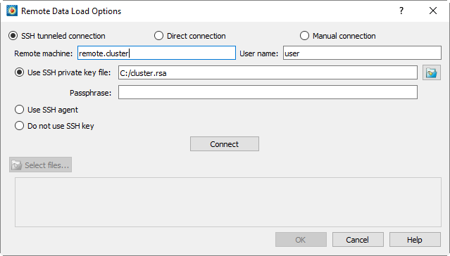
| If the Load Remote Data option is not in the File menu you may need to install libssh2 (Linux only). |
| The first time you use Load Remote Data on Windows, Windows may display a dialog asking you to allow Tecplot 360 to listen for connections. You must grant this permission to allow Tecplot 360 to load remote data. |
The Remote Data Load Options dialog offers three ways to connect to the remote SZL Server:
-
- Uses a secure shell (SSH) connection to carry the data from the server to the workstation so it can be visualized in Tecplot 360. As long as you can connect to the remote host via SSH, you can visualize data from a SZL Server running on that host; the SSH connection is all that is needed. This minimizes any possible network and workstation complications.
-
- May offer better performance than a SSH tunnel, but with less security, because the data is not encrypted. (A SSH connection still must be established to start the server, but the actual data is sent to the workstation without encryption.) The remote host must be able to establish a connection to arbitrary ports on the visualization workstation, which may require setup from a network administrator or may even be disallowed entirely at your site.
You might use Direct Connection mode if your network is already secure (for example, when using a VPN or WAN) and the encryption provided by SSH would be redundant, or if performance is paramount.
-
- This mode allows you to establish a SZL Server session by manually issuing a command on the remote host. Each time you establish a manual connection, Tecplot 360 provides you with an appropriate command that can be used for this purpose.
By default, SZL Server connection is made directly from the remote host to the workstation as in Direct Connection mode described above. However, you can also establish an SSH tunnel manually and run your SZL Server session through it. See Manual Connection Mode for details.
If you are using either of the first two modes, choose it in the dialog, then specify:
-
The hostname or IP address of the remote host
-
Your username on that host
-
How you wish Tecplot 360 to authenticate to the remote host, using one of these options:
-
Your private key file (specify the file by entering the path or by clicking "…"). If your key is protected by a passphrase, enter it in the field provided.
-
A key manager: ssh-agent (or PuTTY’s Pageant utility on Windows).
-
Without a key (you will be prompted for a password when you connect)
-
Then click the button to establish the connection. This may take a few seconds.
| If you are using Manual Connection mode, you will instead see a small window indicating the command you must execute on the remote host to establish the connection. See Manual Connection Mode for details on using this mode. |
Once the connection has been established, the button becomes enabled. Click to choose a file to open. The Select File dialog appears.
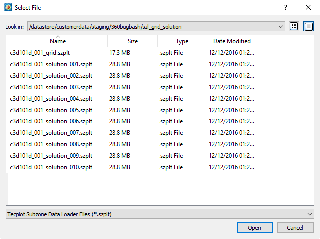
| All remote files open at any one time must be opened from the same directory on the same remote host. You cannot append data using remote files. |
After you choose the files you wish to open and click , you return to the Load Remote Data dialog with those files listed in the bottom panel. Click to proceed with opening the files. Tecplot 360 opens the files and displays the initial plot.
Manual Connection Mode
In Manual Connection mode, you establish an SSH connection to the remote host yourself, then start the server and tell it how to connect back to the Tecplot 360 client running on your workstation. This is useful for unusual network configurations and for those who require complete control.
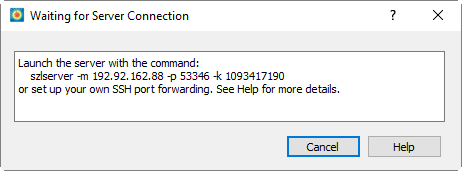
When you click in the Remote Data Load options with the mode set to Manual Connection, Tecplot 360 displays the Waiting For Server Connection dialog. This dialog remains open until you establish the connection from the remote host. To do this, you must issue a command on the host to start SZL Server and tell it how to connect to Tecplot 360 on the client workstation.
The szlserver command shown in the dialog can be copied and pasted into your remote
command line session (established with the ssh command on Linux or Mac, or
a GUI client like PuTTY on Windows). Usually, you will establish a new SSH connection,
but it is possible to use an existing one (see the Note at the end of this section).
For this example, we will establish a new connection.
When invoked using the provided szlserver command, SZL Server establishes a direct,
unencrypted connection to the workstation (as in Direct Connection mode). This requires
that arbitrary ports on your workstation be accessible from the server, which may
require network administrator support or be disallowed entirely at your site.
If it is not possible for the server to connect to the workstation, or if you wish the
session to be encrypted, you can manually tunnel the connection over an SSH connection.
You will need to know the port number on which Tecplot 360 is waiting for the connection.
This is the number following the -p flag in the szlserver command shown in the
Waiting For Server Connection dialog.
You should note the session key, which is the number following -k. The session key is
a random number that is changed for each connection; it is used to verify that the
connection is being made to the correct workstation. When you issue the szlserver
command on the remote host, you must use the session key displayed in the Waiting For
Server Connection dialog.
In the example dialog shown here, Tecplot 360 is listening on port 49767. So you need to establish a tunnel from port 49767 on the remote host to port 49767 on your workstation.
|
You may use a different port number on the remote host if the port you wish to use is already in use on that system, but this is quite rare. If there is a port conflict, it is probably best to close the Load Remote Data Options dialog and try again; Tecplot 360 chooses a different port each time you open the dialog. Alternatively, specify 0 for the remote port; ssh will choose an available port for you and tell you what it is. Valid port numbers range from 1024-65535. Ports with numbers less than 1024 can only be opened by the remote host’s root user. |
On Linux or Mac systems, you can create the tunnel using the -R option with the
ssh command line client. In this command, localhost refers to the
workstation running Tecplot 360, the client of the ssh connection (the
hostname is resolved on the client end).
ssh -R 49767:localhost:49767 username@remote.hostIf you are using a server port number different from the workstation port, the server
port number should be the first number after the -R. For example, if you have decided
to use port 4242 for the server end of the tunnel, the ssh command would be:
ssh -R 4242:localhost:49767 username@remote.hostOn Windows, you can set up port forwarding in PuTTY on the page.
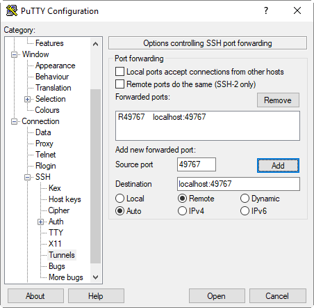
Enter (in this example) 49767 for the source port, localhost:49767 as the
destination, and choose the Remote radio button. (If you are using a different port
number on the server than on the workstation, it goes in the Source Port field.) Then
click to add the tunnel to the forwarded ports list. When you click
to establish the SSH connection, the tunnel is created along with it.
One you have established an SSH connection with the remote host, incorporating a
tunnel, you can issue the szlserver command on the remote host. However, instead of
specifying the address of the client workstation after -m, specify localhost. This
will instruct SZL Server to connect to the host’s end of the tunnel, which will forward
the connection to the workstation.
szlserver -m localhost -p 49767 -k 1443240310If you are using a different port number on the remote host, specify this after -p.
For example, if you are using port 4242 for the remote end of the tunnel, use:
szlserver -m localhost -p 4242 -k 1443240310|
On Windows, PuTTY lets you add tunnels to an existing connection. Simply click the icon in your SSH terminal’s upper left corner, choose from the menu, and navigate to as if you were setting up a new connection. From there, you can remove any obsolete port forwarding and add new tunnels as needed. On Linux and Mac, you can type This feature may not be available depending on SSH client configuration. If it is not available, simply open a new terminal window and establish a new SSH connection incorporating the desired tunnelling. |
Interactive Authentication and Unattended Operation
Depending on your organization’s network and security policies, you might need to enter information to prove your identity when connecting to a SZL Server via SSH. This information might include:
-
An account password, if you are not using a key pair
-
A passphrase for a protected private key or key store
-
A security code from an authentication token or app (such as Google Authenticator)
Or, if you are using Manual Connection mode, you must enter a command on the remote host in order to establish the connection.
Tecplot 360 prompts you to enter any necessary authentication information or take other action to establish the connection to SZL Server as necessary. When running Tecplot 360 interactively—with its full graphical user interface—a dialog appears to request your password or to ask you to perform other steps.
When you record a connection to a SZL Server in a macro, the most that is ever stored in the macro is the path to your private key file. The key itself and its passphrase are never stored; likewise, if you are using password authentication, the password is not stored. Therefore, for batch operations—such as running a macro from the command line—the Linux and Mac versions of Tecplot 360 will prompt you to enter this information in the terminal window if it is necessary.
Similarly, the macro file does not store any manual steps you do when establishing a connection via Manual mode, because these steps are done outside Tecplot 360. So when connecting via the Manual connection mode in batch mode, you will be instructed in the terminal to establish the connection, and Tecplot 360 will wait for the connection to be established.
The Windows version of Tecplot 360 detaches from the text console and cannot read or
write to the command line window. Therefore, the $!READDATASET macro instruction
fails in batch mode on Windows if any additional information or action is needed to
connect to the remote host. (The file batch.log will include an error message
in this case.) You must use Tecplot 360 in interactive mode to be able to open such data
sets on Windows.
True unattended operation requires use of the SSH Tunneled or Direct Connection modes with SSH key pairs without passphrases or other interactive requirements. In this case, all platforms can access the data files in batch mode without difficulty.
