Annotations
Text
Text
- class tecplot.annotation.Text(uid, frame)[source]
Text annotation.
Attributes
Anchor location of this
Textobject.Angle of the text box in degrees.
Index of the attached fieldmap or linemap.
The frame and area around this
Textobject.Typeface properties for a
Textobject.Spacing between lines in the text box.
Anchor position of the
Text.Position coordinate system of the
Textobject.The text to be displayed in a text box.
Normal or LaTeX text type setting.
- Text.anchor
Anchor location of this
Textobject.Specify the anchor point, or fixed point, for the text object. As the text object grows or shrinks, the anchor location is fixed, while the rest of the box adjusts to accommodate the new size. (default =
TextAnchor.Left)There are nine possible anchor position points, corresponding to the left, right, and center positions on the headline, midline, and baseline of the text box.
Example showing how to set the anchor of a
Textobject:>>> text = frame.add_text('abc') >>> text.anchor = tecplot.constant.TextAnchor.Center
See also
- Type:
- Text.angle
Angle of the text box in degrees.
The text angle is the orientation of the text relative to the axis. The angle is measured in degrees counter-clockwise from horizontal. Horizontal text is at zero degrees; vertical text is at 90 degrees.
Example showing how to set the angle of a
Textobject:>>> text = frame.add_text('abc') >>> text.angle = 45
- Type:
float(degrees counter-clockwise)
- Text.attached_map_index
Index of the attached fieldmap or linemap.
Example showing how to set the attached object
Indexof aTextobject:>>> text = frame.add_text("abc") >>> text.attached_map_index = 1
- Text.box
The frame and area around this
Textobject.The text box is a rectangular frame drawn around the text. Note that in order to show the text box, you must set TextBox.type to a value other than
constant.TextBox.None_.Example showing how to enable the text box for a
Textobject:>>> text = frame.add_text("abc") >>> text.box.type = tecplot.constant.TextBox.Filled
- Type:
- Text.clipping
Clippingproperties of theTextClipping refers to displaying only that portion of an object that falls within a specified clipping region of the plot. If you have specified your text position in the Frame coordinate system, the
Textwill be clipped to the frame. Default:Clipping.ClipToViewport.If you have specified the Grid coordinate system, you can choose to clip your
Textto the frame or the viewport. The size of the viewport depends on the plot type as follows:- 3D Cartesian - The viewport is the same as the frame, so viewport
clipping is the same as frame clipping.
- 2D Cartesian/XY Line - The viewport is defined by the extents of
the X and Y axes.
- Polar Line/Sketch - By default, the viewport is the same as the
frame.
Example showing how to set the clipping of a
Text:>>> text = frame.add_text('abc') >>> text.clipping = tecplot.constant.Clipping.ClipToFrame
- Type:
- Text.color
-
Default:
Color.Black. Example showing how to set theColorof aTextobject:>>> text = frame.add_text("abc") >>> text.color = tecplot.constant.Color.Blue
- Type:
- Text.font
Typeface properties for a
Textobject.Example usage:
>>> text = frame.add_text('abc')
>>> text.font.typeface = 'Times'
- Type:
- Text.line_spacing
Spacing between lines in the text box.
Line spacing is dependent on the height of the text and the size unit system in which it is drawn. This example shows how to set the line spacing of a
Textobject:>>> text = frame.add_text('abc') >>> text.line_spacing = 4
- Type:
float(default = 1.0)
- Text.position
Anchor position of the
Text.This is the position of the
Texton theFrameand will be \((x,y)\) or \((\theta,r)\) depending on the plot type (Cartesian or polar). This example shows how to set the anchor position of aTextobject:>>> text = frame.add_text("abc") >>> text.position = (1.0, 2.0)
See also
- Type:
- Text.position_coordinate_system
Position coordinate system of the
Textobject.The text object may be positioned using either the grid coordinate system or the frame coordinate system and must be one of
CoordSys.FrameorCoordSys.GridIf the position_coordinate_system is
CoordSys.Frame, then the size_units property must beUnits.FrameorUnits.Point.The text object’s position and text height are adjusted so that it remains identical to its visual appearance in the original coordinate and unit system.
If the size units are
Units.Gridand the position coordinate system is changed toCoordSys.Frame, then the size units will be changed toUnits.Frame. (default = CoordSys.Frame)Example showing how to set the position coordinate system for a
Textobject:>>> from tecplot.constant import CoordSys >>> text = frame.add_text("abc") >>> text.position_coordinate_system = CoordSys.Grid
Example showing side effect if size units are
CoordSys.Gridand the coordinate system is changed toCoordSys.Frame:>>> from tecplot.constant import CoordSys, Units >>> text = frame.add_text("abc") >>> text.font.size_units = Units.Grid >>> text.position_coordinate_system = CoordSys.Frame >>> text.position_coordinate_system CoordSys.Frame >>> text.font.size_units Units.Frame
- Type:
- Text.scope
The
Scope(local or global) of theText.Annotations with local scope are displayed only in the
framein which they are created. If the annotation is defined as havingglobalscope, it will appear in all “like”frames. That is, those frames using the same data set as the one in which the annotation was created. (default:Scope.Local)Example showing how to set the scope of a
Textobject:>>> text = frame.add_text("abc") >>> text.scope = tecplot.constant.Scope.Global
- Type:
- Text.text_string
The text to be displayed in a text box.
You can embed Greek, Math, and User-defined characters into English-font strings by enclosing them with text formatting tags, together with the keyboard characters.
The text formatting tags and their effects are as follows. Format tags are not case sensitive and may be either upper or lower case:
<b>…</b> - Boldface
<i>…</i> - Italic
<verbatim>…</verbatim> - Verbatim
<sub>…</sub> - Subscripts
<sup>…</sup> - Superscripts
<greek>…</greek> - Greek font.
<math>…</math> - Math font.
<userdef>…</userdef> - User-defined font.
<helvetica>…</helvetica> - Helvetica font.
<times>…</times> - Times font.
<courier>…</courier> - Courier font.
Not all fonts have Bold and/or Italic variants. For fonts that do not have these styles, the <b> and/or <i> tags may have no effect.
Embedding and escaping special characters work only in English-font text; they have no effect in text created in Greek, Math, or User-defined character sets.
You can produce subscripts or superscripts by enclosing any characters with <sub>…</sub> or <sup>…</sup>, respectively. Tecplot 360 has only one level of superscripts and subscripts. Expressions requiring additional levels must be created by hand using multiple text objects. If you alternate subscripts and superscripts, Tecplot 360 positions the superscript directly above the subscript. To produce consecutive superscripts, enclose all superscript characters in a single pair of tags.
To insert a tag into text literally, precede the first angle bracket with a backslash (“”). To insert a backslash in the text, just type two backslashes (”"). This example shows how to set the text string of a
Textobject:>>> text = frame.add_text('abc') >>> text.text_string 'abc' >>> text.text_string ='def' >>> text.text_string 'def'
- Type:
- Text.type
Normal or LaTeX text type setting.
Possible values are
TextType.RegularorTextType.LaTeX:>>> text = frame.add_text(r'\alpha') >>> text.type = TextType.LaTeX
- Type:
TextBox
- class tecplot.annotation.TextBox(text)[source]
The box surrounding a
Textobject.Attributes
Border line color of the text box.
Background fill color of the text box.
Border line thickness.
Margin between the text and the surrounding border.
Style of the text box fill area and border.
- TextBox.color
Border line color of the text box.
Default:
Color.Black. Example showing how to set the outline color of thetext boxfor aTextobject:>>> from tecplot.constant import Color, TextBox >>> text = frame.add_text("abc") >>> text.box.type = TextBox.Filled >>> text.box.color = Color.Blue
- Type:
- TextBox.corner_locations
tuple: Position of the four corners of thetext box.Note: This property is read-only.
The tuple consists of 8
floats:x1: X-Coordinate for bottom left corner
y1: Y-Coordinate for bottom left corner
x2: X-Coordinate for bottom right corner
y2: Y-Coordinate for bottom right corner
x3: X-Coordinate for upper right corner
y3: Y-Coordinate for upper right corner
x4: X-Coordinate for upper left corner
y4: Y-Coordinate for upper left corner
There is no default, position will vary with text box properties. Example showing how to query position of the
text boxfor aTextobject. The valuesx1, ..., y4`contain the corners of the text box:>>> text = frame.add_text("abc") >>> text.box.type = tecplot.constant.TextBox.Filled >>> x1,y1,x2,y2,x3,y3,x4,y4 = text.box.corner_locations
- TextBox.fill_color
Background fill color of the text box.
Example showing how to set the fill color of the
text boxfor aTextobject:>>> text = frame.add_text("abc") >>> text.box.type = TextBox.Filled >>> text.box.fill_color = tecplot.constant.Color.Blue
- Type:
- TextBox.line_thickness
Border line thickness.
Must be greater than 0, default:
0.1. Example showing how to set the line thickness of thetext box:>>> text = frame.add_text("abc") >>> text.box.line_thickness = 0.5
- Type:
- TextBox.margin
Margin between the text and the surrounding border.
Specify the margin as a percentage of the text character height. Margin must be greater than or equal to 0.0, and may be greater than 100. (default = 20.0)
Example showing how to set the margin of the
text boxfor aTextobject:>>> text = frame.add_text("abc") >>> text.box.type = tecplot.constant.TextBox.Filled >>> text.box.margin = 0.5
- Type:
- TextBox.type
Style of the text box fill area and border.
The text box type can be set to the following:
None_- (default) No box is drawn around the text.- Filled - A filled box around the text which is opaque. if you
place it over another Tecplot 360 object, the underlying object cannot be seen.
Hollow - A plain box around the text.
Example showing how to set the type of the text box for a
TextBoxobject:>>> text = frame.add_text("abc") >>> text.box.type = tecplot.constant.TextBox.Filled
- Type:
TextFont
- class tecplot.annotation.TextFont(text)[source]
Typeface and font settings for a
Textobject.Attributes
Use bold typeface in the
Textobject.Use italic typeface of the
Textobject.The text size in the currently defined text size units.
Units of the text character height.
The font family used by the
Textobject.
- TextFont.bold
Use bold typeface in the
Textobject.Example showing how to set the bold property of a
Textobject:>>> text = frame.add_text('abc') >>> text.font.bold = True
- Type:
- TextFont.italic
Use italic typeface of the
Textobject.Example showing how to set the italic property of a
Textobject:>>> text = frame.add_text('abc') >>> text.font.italic = True
- Type:
- TextFont.size
The text size in the currently defined text size units.
Example showing how to set the text size of a
Textobject:>>> text = frame.add_text('abc') >>> text.font.size_units = tecplot.constant.Units.Point >>> text.font.size = 14
- Type:
- TextFont.size_units
Units of the text character height.
Unitsmay be one of the following:Units.Point: Specify character height in points.Units.Frame: Specify character height as a percentage of frameheight
Units.Grid: Specify character height in grid units.
(default =
Units.Point)Note
One point is 1/72nd of an inch.
Units.Gridis available only if position_coordinate_system is
- The position coordinate system will be changed to
CoordSys.Grid if size units is set to
Units.Grid
- The position coordinate system will be changed to
Example showing how to set the units of the character height for a
Textobject:>>> from tecplot.constant import CoordSys >>> text = frame.add_text("abc") >>> text.position_coordinate_system = CoordSys.Grid >>> text.font.size_units = Units.Point
- Type:
- TextFont.typeface
The font family used by the
Textobject.For consistency across various platforms, Tecplot 360 guarantees that the following standard typeface names are available:
“Helvetica”
“Times”
“Courier”
“Greek”
“Math”
“User Defined”
Other typefaces may or may not be available depending on the TrueType fonts available. If the typeface or style is not available, a suitable replacement will be selected. This example shows how to set the typeface of a
Textobject to ‘Times’:>>> text = frame.add_text('abc') >>> text.font.typeface = 'Times'
- Type:
Geometric Shapes
Circle
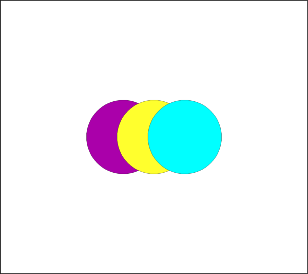
- class tecplot.annotation.Circle(uid, frame)[source]
A circle annotation attached to a
Frame.See also
import tecplot as tp
from tecplot.constant import *

frame = tp.active_frame()

circle0 = frame.add_circle((40, 50), 12, CoordSys.Frame)
circle1 = frame.add_circle((50, 50), 12, CoordSys.Frame)
circle2 = frame.add_circle((60, 50), 12, CoordSys.Frame)

circle0.fill_color = Color.Magenta
circle1.fill_color = Color.Yellow
circle2.fill_color = Color.Cyan

tp.export.save_png('circle.png', 600)
Attributes
Index to the associated fieldmap or linemap.
Clip geometry to the axes or frame for 2D plots.
Line
Color.Draw before or after the data.
Background fill color.
Pattern used for drawing lines or edges.
Thickness of lines or edges.
An associated macro function.
Number of points to use when creating the curved shape.
Length of the line pattern.
Position coordinate system.
Length of the radius.
Display annotation in all frames with the same data.
The type of this annotation (read-only).
- Circle.attached_map_index
Index to the associated fieldmap or linemap.
This property allows an annotation to follow the same active/inactive state as another plot object so their visibility can be changed together. Attach this annotation to a fieldmap or linemap using the object’s index property. Geometries and images that are attached to an inactive or non-existent zone are not displayed. Example usage assuming an annotation variable
anno:>>> anno.attached_map_index = plot.fieldmap(2).index
- Circle.clipping
Clip geometry to the axes or frame for 2D plots.
Clipping refers to displaying only that portion of an object that falls within a specified clipping region of the plot. If you have specified the position in the Frame coordinate system, the Annotations will be clipped to the frame. Default:
Clipping.ClipToViewport.If you have specified the Grid coordinate system, you can choose to clip your Annotations to the frame or the viewport. The size of the viewport depends on the plot type as follows:
- 3D Cartesian - The viewport is the same as the frame, so viewport
clipping is the same as frame clipping.
- 2D Cartesian/XY Line - The viewport is defined by the extents of
the X and Y axes.
- Polar Line/Sketch - By default, the viewport is the same as the
frame.
Warning
For 3D and line plots the viewport is the same as the frame and so clipping to the viewport or the frame will have no apparent affect. In cartesian 2D plots, clipping to the axes (
Clipping.ClipToViewport) is only available when the position coordinate system isCoordSys.Grid.Example of clipping a circle to the frame:
>>> from tecplot.constant import Clipping, CoordSys
>>> geom = frame.add_circle((0.5, 0.5), 0.55, CoordSys.Grid)
>>> geom.clipping = Clipping.ClipToFrame
- Type:
- Circle.color
Line
Color.This example shows how to change the edge or line
Colorto red:>>> from tecplot.constant import Color, CoordSys >>> geom = frame.add_circle((50, 50), 10, CoordSys.Frame) >>> geom.color = Color.Red
- Type:
- Circle.draw_order
Draw before or after the data.
Annotations can be drawn either before or after the data. If a geometry or image is drawn before the data, the plot layers, such as mesh, contour lines, etc. will be drawn on top of the geometry. Otherwise, the annotation will be drawn last, potentially obscuring the data.
Note
Tecplot 360 draws all geometries and images first, in the order they were added, then all text.
Example usage assuming an annotation variable
anno:>>> from tecplot.constant import DrawOrder >>> anno.draw_order = DrawOrder.BeforeData
- Type:
- Circle.fill_color
Background fill color.
This example shows how to change the area fill
Colorto red. To turn off filling the geometry, set this attribute toNone:>>> from tecplot.constant import Color, CoordSys >>> geom = frame.add_circle((50, 50), 10, CoordSys.Frame) >>> geom.fill_color = Color.Red
- Type:
- Circle.line_pattern
Pattern used for drawing lines or edges.
This example shows how to change the line pattern:
>>> from tecplot.constant import CoordSys, LinePattern
>>> geom = frame.add_circle((50, 50), 10, CoordSys.Frame)
>>> geom.line_pattern = LinePattern.DashDot
- Type:
- Circle.line_thickness
Thickness of lines or edges.
This example shows how to change the line thickness:
>>> from tecplot.constant import CoordSys
>>> geom = frame.add_circle((50, 50), 10, CoordSys.Frame)
>>> geom.line_thickness = 4.0
- Type:
- Circle.macro_function
An associated macro function.
All geometry or image annotations may be linked to a macro function. This macro function is called when you hold down the Control key (Command key on Mac OS X) and click the right mouse button on the text, geometry or image in the frame.
In order to be attached to a text or geometry object, the macro function must be a “retained” macro function. A macro function is “retained” via either of the following scenarios:
running a macro file that contains the required macro functions
including it in your tecplot.mcr file (which is run at start up, making it a special case of the preceding scenario)
In both cases, the macro function is defined using the $!MACROFUNCTION macro command. Refer to “$!MACROFUNCTION…$!ENDMACROFUNCTION” on page 157 in the Tecplot Macro Scripting Guide for additional information.
Example usage assuming an annotation variable
anno:>>> anno.macro_function = 'MYMACROFUNCTION'
To run this function from PyTecplot it is neccessary to pass the function to a call to
macro.execute_function():>>> tecplot.macro.execute_function(anno.macro_function)
- Type:
- Circle.num_points
Number of points to use when creating the curved shape.
This is the number of segments along the edge plus one. Example usage:
>>> from tecplot.constant import CoordSys
>>> geom = frame.add_circle((50, 50), 10, CoordSys.Frame)
>>> geom.num_points = 300
- Type:
- Circle.pattern_length
Length of the line pattern.
This example shows how to change the pattern length:
>>> from tecplot.constant import CoordSys
>>> geom = frame.add_circle((50, 50), 10, CoordSys.Frame)
>>> geom.pattern_length = 1.2
- Type:
- Circle.position
-
This is the origin of the annotation and will be \((x,y)\) or \((\theta,r)\) depending on the plot type. Example usage assuming an annotation variable
anno:>>> anno.position = (3, 4)
- Circle.position_coordinate_system
Position coordinate system.
The object may be positioned using either the grid coordinate system or the frame coordinate system and must be one of
CoordSys.FrameorCoordSys.Grid:CoordSys.Frame: The geometry is always displayed at constant size and position when you zoom in or out of the plot.CoordSys.Grid: The geometry resizes and moves with the data grid. However, the geometry remains fixed when you rotate the plot. Changing the center of rotation may cause the geometry to move.
Example usage assuming an annotation variable
anno:>>> from tecplot.constant import CoordSys >>> anno.position_coordinate_system = CoordSys.Frame
- Type:
- Circle.radius
Length of the radius.
This will be in the coordinate system specified by
Circle.position_coordinate_system. This example creates a circle of radius 5 and then doubles it to 10 later:>>> from tecplot.constant import CoordSys >>> geom = frame.add_circle((20, 30), 5, CoordSys.Frame) >>> geom.radius = 10
- Type:
- Circle.scope
Display annotation in all frames with the same data.
Annotations with local scope are displayed only in the
Framein which they are created. If it is defined as havingglobalscope, it will appear in all “like”frames. That is, those frames using the same data set as the one in which the annotation was created. (default:Scope.Local)Example usage assuming an annotation variable
anno:>>> from tecplot.constant import Scope >>> anno.scope = Scope.Global
- Type:
- Circle.type
The type of this annotation (read-only).
This is the generic type information for geometry and image annotations. This is a read-only parameter and is used, in combination with position_coordinate_system to determine the actual return types of the iterators
Frame.geometries()andFrame.images():>>> frame.add_image('image.png', (1, 1), 5) >>> frame.add_circle((0,0), 1, CoordSys.Grid) >>> frame.add_square((0,0), 1, CoordSys.Grid) >>> for anno in frame.images(): ... print(anno.type) ... GeomType.Image >>> for anno in frame.geometries(): ... print(anno.type) ... GeomType.Circle GeomType.Square
- Type:
Ellipse
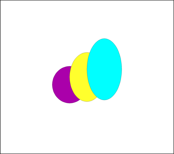
- class tecplot.annotation.Ellipse(uid, frame)[source]
An ellipse annotation attached to a
Frame.See also
import tecplot as tp
from tecplot.constant import *

frame = tp.active_frame()

ellipse0 = frame.add_ellipse((40, 45), (10, 12), CoordSys.Frame)
ellipse1 = frame.add_ellipse((50, 50), (10, 16), CoordSys.Frame)
ellipse2 = frame.add_ellipse((60, 55), (10, 20), CoordSys.Frame)

ellipse0.fill_color = Color.Magenta
ellipse1.fill_color = Color.Yellow
ellipse2.fill_color = Color.Cyan

tp.export.save_png('ellipse.png', 600)
Attributes
Index to the associated fieldmap or linemap.
Clip geometry to the axes or frame for 2D plots.
Line
Color.Draw before or after the data.
Background fill color.
Pattern used for drawing lines or edges.
Thickness of lines or edges.
An associated macro function.
Number of points to use when creating the curved shape.
Length of the line pattern.
Position coordinate system.
Display annotation in all frames with the same data.
Size \((h_{axis}, v_{axis})\) of the ellipse.
The type of this annotation (read-only).
- Ellipse.attached_map_index
Index to the associated fieldmap or linemap.
This property allows an annotation to follow the same active/inactive state as another plot object so their visibility can be changed together. Attach this annotation to a fieldmap or linemap using the object’s index property. Geometries and images that are attached to an inactive or non-existent zone are not displayed. Example usage assuming an annotation variable
anno:>>> anno.attached_map_index = plot.fieldmap(2).index
- Ellipse.clipping
Clip geometry to the axes or frame for 2D plots.
Clipping refers to displaying only that portion of an object that falls within a specified clipping region of the plot. If you have specified the position in the Frame coordinate system, the Annotations will be clipped to the frame. Default:
Clipping.ClipToViewport.If you have specified the Grid coordinate system, you can choose to clip your Annotations to the frame or the viewport. The size of the viewport depends on the plot type as follows:
- 3D Cartesian - The viewport is the same as the frame, so viewport
clipping is the same as frame clipping.
- 2D Cartesian/XY Line - The viewport is defined by the extents of
the X and Y axes.
- Polar Line/Sketch - By default, the viewport is the same as the
frame.
Warning
For 3D and line plots the viewport is the same as the frame and so clipping to the viewport or the frame will have no apparent affect. In cartesian 2D plots, clipping to the axes (
Clipping.ClipToViewport) is only available when the position coordinate system isCoordSys.Grid.Example of clipping a circle to the frame:
>>> from tecplot.constant import Clipping, CoordSys
>>> geom = frame.add_circle((0.5, 0.5), 0.55, CoordSys.Grid)
>>> geom.clipping = Clipping.ClipToFrame
- Type:
- Ellipse.color
Line
Color.This example shows how to change the edge or line
Colorto red:>>> from tecplot.constant import Color, CoordSys >>> geom = frame.add_circle((50, 50), 10, CoordSys.Frame) >>> geom.color = Color.Red
- Type:
- Ellipse.draw_order
Draw before or after the data.
Annotations can be drawn either before or after the data. If a geometry or image is drawn before the data, the plot layers, such as mesh, contour lines, etc. will be drawn on top of the geometry. Otherwise, the annotation will be drawn last, potentially obscuring the data.
Note
Tecplot 360 draws all geometries and images first, in the order they were added, then all text.
Example usage assuming an annotation variable
anno:>>> from tecplot.constant import DrawOrder >>> anno.draw_order = DrawOrder.BeforeData
- Type:
- Ellipse.fill_color
Background fill color.
This example shows how to change the area fill
Colorto red. To turn off filling the geometry, set this attribute toNone:>>> from tecplot.constant import Color, CoordSys >>> geom = frame.add_circle((50, 50), 10, CoordSys.Frame) >>> geom.fill_color = Color.Red
- Type:
- Ellipse.line_pattern
Pattern used for drawing lines or edges.
This example shows how to change the line pattern:
>>> from tecplot.constant import CoordSys, LinePattern
>>> geom = frame.add_circle((50, 50), 10, CoordSys.Frame)
>>> geom.line_pattern = LinePattern.DashDot
- Type:
- Ellipse.line_thickness
Thickness of lines or edges.
This example shows how to change the line thickness:
>>> from tecplot.constant import CoordSys
>>> geom = frame.add_circle((50, 50), 10, CoordSys.Frame)
>>> geom.line_thickness = 4.0
- Type:
- Ellipse.macro_function
An associated macro function.
All geometry or image annotations may be linked to a macro function. This macro function is called when you hold down the Control key (Command key on Mac OS X) and click the right mouse button on the text, geometry or image in the frame.
In order to be attached to a text or geometry object, the macro function must be a “retained” macro function. A macro function is “retained” via either of the following scenarios:
running a macro file that contains the required macro functions
including it in your tecplot.mcr file (which is run at start up, making it a special case of the preceding scenario)
In both cases, the macro function is defined using the $!MACROFUNCTION macro command. Refer to “$!MACROFUNCTION…$!ENDMACROFUNCTION” on page 157 in the Tecplot Macro Scripting Guide for additional information.
Example usage assuming an annotation variable
anno:>>> anno.macro_function = 'MYMACROFUNCTION'
To run this function from PyTecplot it is neccessary to pass the function to a call to
macro.execute_function():>>> tecplot.macro.execute_function(anno.macro_function)
- Type:
- Ellipse.num_points
Number of points to use when creating the curved shape.
This is the number of segments along the edge plus one. Example usage:
>>> from tecplot.constant import CoordSys
>>> geom = frame.add_circle((50, 50), 10, CoordSys.Frame)
>>> geom.num_points = 300
- Type:
- Ellipse.pattern_length
Length of the line pattern.
This example shows how to change the pattern length:
>>> from tecplot.constant import CoordSys
>>> geom = frame.add_circle((50, 50), 10, CoordSys.Frame)
>>> geom.pattern_length = 1.2
- Type:
- Ellipse.position
-
This is the origin of the annotation and will be \((x,y)\) or \((\theta,r)\) depending on the plot type. Example usage assuming an annotation variable
anno:>>> anno.position = (3, 4)
- Ellipse.position_coordinate_system
Position coordinate system.
The object may be positioned using either the grid coordinate system or the frame coordinate system and must be one of
CoordSys.FrameorCoordSys.Grid:CoordSys.Frame: The geometry is always displayed at constant size and position when you zoom in or out of the plot.CoordSys.Grid: The geometry resizes and moves with the data grid. However, the geometry remains fixed when you rotate the plot. Changing the center of rotation may cause the geometry to move.
Example usage assuming an annotation variable
anno:>>> from tecplot.constant import CoordSys >>> anno.position_coordinate_system = CoordSys.Frame
- Type:
- Ellipse.scope
Display annotation in all frames with the same data.
Annotations with local scope are displayed only in the
Framein which they are created. If it is defined as havingglobalscope, it will appear in all “like”frames. That is, those frames using the same data set as the one in which the annotation was created. (default:Scope.Local)Example usage assuming an annotation variable
anno:>>> from tecplot.constant import Scope >>> anno.scope = Scope.Global
- Type:
- Ellipse.size
Size \((h_{axis}, v_{axis})\) of the ellipse.
This is the horizontal and vertical axis lengths of the ellipse and will be in the coordinate system specified by
Ellipse.position_coordinate_system. This example creates an ellipse with \((h_{axis}, v_{axis})\) of \((5, 10)\) and changes it to \((10, 20)\) later:>>> from tecplot.constant import CoordSys >>> geom = frame.add_ellipse((50, 50), (5, 10), CoordSys.Frame) >>> geom.size = (10, 20)
- Type:
- Ellipse.type
The type of this annotation (read-only).
This is the generic type information for geometry and image annotations. This is a read-only parameter and is used, in combination with position_coordinate_system to determine the actual return types of the iterators
Frame.geometries()andFrame.images():>>> frame.add_image('image.png', (1, 1), 5) >>> frame.add_circle((0,0), 1, CoordSys.Grid) >>> frame.add_square((0,0), 1, CoordSys.Grid) >>> for anno in frame.images(): ... print(anno.type) ... GeomType.Image >>> for anno in frame.geometries(): ... print(anno.type) ... GeomType.Circle GeomType.Square
- Type:
Rectangle
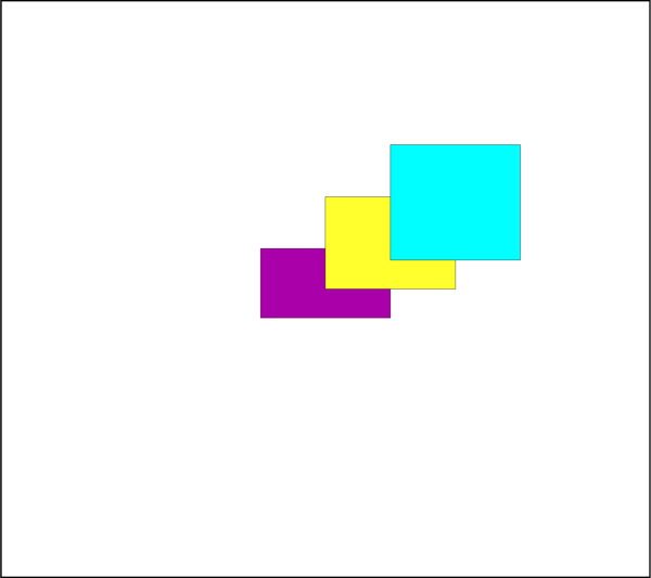
- class tecplot.annotation.Rectangle(uid, frame)[source]
A rectangle annotation attached to a
Frame.See also
import tecplot as tp
from tecplot.constant import *

frame = tp.active_frame()

rectangle0 = frame.add_rectangle((40, 45), (20, 12), CoordSys.Frame)
rectangle1 = frame.add_rectangle((50, 50), (20, 16), CoordSys.Frame)
rectangle2 = frame.add_rectangle((60, 55), (20, 20), CoordSys.Frame)

rectangle0.fill_color = Color.Magenta
rectangle1.fill_color = Color.Yellow
rectangle2.fill_color = Color.Cyan

tp.export.save_png('rectangle.png', 600)
Attributes
Index to the associated fieldmap or linemap.
Clip geometry to the axes or frame for 2D plots.
Line
Color.Draw before or after the data.
Background fill color.
Pattern used for drawing lines or edges.
Thickness of lines or edges.
An associated macro function.
Length of the line pattern.
Position coordinate system.
Display annotation in all frames with the same data.
Size \((width, height)\) of the rectangle.
The type of this annotation (read-only).
- Rectangle.attached_map_index
Index to the associated fieldmap or linemap.
This property allows an annotation to follow the same active/inactive state as another plot object so their visibility can be changed together. Attach this annotation to a fieldmap or linemap using the object’s index property. Geometries and images that are attached to an inactive or non-existent zone are not displayed. Example usage assuming an annotation variable
anno:>>> anno.attached_map_index = plot.fieldmap(2).index
- Rectangle.clipping
Clip geometry to the axes or frame for 2D plots.
Clipping refers to displaying only that portion of an object that falls within a specified clipping region of the plot. If you have specified the position in the Frame coordinate system, the Annotations will be clipped to the frame. Default:
Clipping.ClipToViewport.If you have specified the Grid coordinate system, you can choose to clip your Annotations to the frame or the viewport. The size of the viewport depends on the plot type as follows:
- 3D Cartesian - The viewport is the same as the frame, so viewport
clipping is the same as frame clipping.
- 2D Cartesian/XY Line - The viewport is defined by the extents of
the X and Y axes.
- Polar Line/Sketch - By default, the viewport is the same as the
frame.
Warning
For 3D and line plots the viewport is the same as the frame and so clipping to the viewport or the frame will have no apparent affect. In cartesian 2D plots, clipping to the axes (
Clipping.ClipToViewport) is only available when the position coordinate system isCoordSys.Grid.Example of clipping a circle to the frame:
>>> from tecplot.constant import Clipping, CoordSys
>>> geom = frame.add_circle((0.5, 0.5), 0.55, CoordSys.Grid)
>>> geom.clipping = Clipping.ClipToFrame
- Type:
- Rectangle.color
Line
Color.This example shows how to change the edge or line
Colorto red:>>> from tecplot.constant import Color, CoordSys >>> geom = frame.add_circle((50, 50), 10, CoordSys.Frame) >>> geom.color = Color.Red
- Type:
- Rectangle.draw_order
Draw before or after the data.
Annotations can be drawn either before or after the data. If a geometry or image is drawn before the data, the plot layers, such as mesh, contour lines, etc. will be drawn on top of the geometry. Otherwise, the annotation will be drawn last, potentially obscuring the data.
Note
Tecplot 360 draws all geometries and images first, in the order they were added, then all text.
Example usage assuming an annotation variable
anno:>>> from tecplot.constant import DrawOrder >>> anno.draw_order = DrawOrder.BeforeData
- Type:
- Rectangle.fill_color
Background fill color.
This example shows how to change the area fill
Colorto red. To turn off filling the geometry, set this attribute toNone:>>> from tecplot.constant import Color, CoordSys >>> geom = frame.add_circle((50, 50), 10, CoordSys.Frame) >>> geom.fill_color = Color.Red
- Type:
- Rectangle.line_pattern
Pattern used for drawing lines or edges.
This example shows how to change the line pattern:
>>> from tecplot.constant import CoordSys, LinePattern
>>> geom = frame.add_circle((50, 50), 10, CoordSys.Frame)
>>> geom.line_pattern = LinePattern.DashDot
- Type:
- Rectangle.line_thickness
Thickness of lines or edges.
This example shows how to change the line thickness:
>>> from tecplot.constant import CoordSys
>>> geom = frame.add_circle((50, 50), 10, CoordSys.Frame)
>>> geom.line_thickness = 4.0
- Type:
- Rectangle.macro_function
An associated macro function.
All geometry or image annotations may be linked to a macro function. This macro function is called when you hold down the Control key (Command key on Mac OS X) and click the right mouse button on the text, geometry or image in the frame.
In order to be attached to a text or geometry object, the macro function must be a “retained” macro function. A macro function is “retained” via either of the following scenarios:
running a macro file that contains the required macro functions
including it in your tecplot.mcr file (which is run at start up, making it a special case of the preceding scenario)
In both cases, the macro function is defined using the $!MACROFUNCTION macro command. Refer to “$!MACROFUNCTION…$!ENDMACROFUNCTION” on page 157 in the Tecplot Macro Scripting Guide for additional information.
Example usage assuming an annotation variable
anno:>>> anno.macro_function = 'MYMACROFUNCTION'
To run this function from PyTecplot it is neccessary to pass the function to a call to
macro.execute_function():>>> tecplot.macro.execute_function(anno.macro_function)
- Type:
- Rectangle.pattern_length
Length of the line pattern.
This example shows how to change the pattern length:
>>> from tecplot.constant import CoordSys
>>> geom = frame.add_circle((50, 50), 10, CoordSys.Frame)
>>> geom.pattern_length = 1.2
- Type:
- Rectangle.position
-
This is the origin of the annotation and will be \((x,y)\) or \((\theta,r)\) depending on the plot type. Example usage assuming an annotation variable
anno:>>> anno.position = (3, 4)
- Rectangle.position_coordinate_system
Position coordinate system.
The object may be positioned using either the grid coordinate system or the frame coordinate system and must be one of
CoordSys.FrameorCoordSys.Grid:CoordSys.Frame: The geometry is always displayed at constant size and position when you zoom in or out of the plot.CoordSys.Grid: The geometry resizes and moves with the data grid. However, the geometry remains fixed when you rotate the plot. Changing the center of rotation may cause the geometry to move.
Example usage assuming an annotation variable
anno:>>> from tecplot.constant import CoordSys >>> anno.position_coordinate_system = CoordSys.Frame
- Type:
- Rectangle.scope
Display annotation in all frames with the same data.
Annotations with local scope are displayed only in the
Framein which they are created. If it is defined as havingglobalscope, it will appear in all “like”frames. That is, those frames using the same data set as the one in which the annotation was created. (default:Scope.Local)Example usage assuming an annotation variable
anno:>>> from tecplot.constant import Scope >>> anno.scope = Scope.Global
- Type:
- Rectangle.size
Size \((width, height)\) of the rectangle.
This is the width and height of the rectangle and will be in the coordinate system specified by
Rectangle.position_coordinate_system. This example creates a rectangle with \((width, height)\) of \((5, 10)\) and changes it to \((10, 20)\) later:>>> from tecplot.constant import CoordSys >>> geom = frame.add_rectangle((50, 50), (5, 10), CoordSys.Frame) >>> geom.size = (10, 20)
- Type:
- Rectangle.type
The type of this annotation (read-only).
This is the generic type information for geometry and image annotations. This is a read-only parameter and is used, in combination with position_coordinate_system to determine the actual return types of the iterators
Frame.geometries()andFrame.images():>>> frame.add_image('image.png', (1, 1), 5) >>> frame.add_circle((0,0), 1, CoordSys.Grid) >>> frame.add_square((0,0), 1, CoordSys.Grid) >>> for anno in frame.images(): ... print(anno.type) ... GeomType.Image >>> for anno in frame.geometries(): ... print(anno.type) ... GeomType.Circle GeomType.Square
- Type:
Square
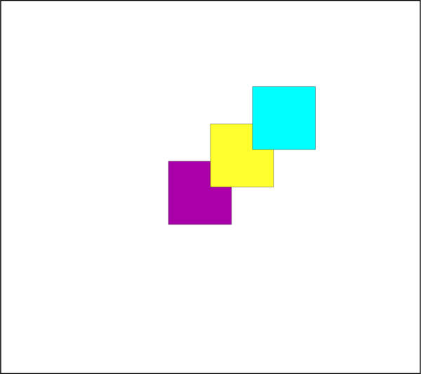
- class tecplot.annotation.Square(uid, frame)[source]
A square annotation attached to a
Frame.See also
import tecplot as tp
from tecplot.constant import *

frame = tp.active_frame()

square0 = frame.add_square((40, 40), 15, CoordSys.Frame)
square1 = frame.add_square((50, 50), 15, CoordSys.Frame)
square2 = frame.add_square((60, 60), 15, CoordSys.Frame)

square0.fill_color = Color.Magenta
square1.fill_color = Color.Yellow
square2.fill_color = Color.Cyan

tp.export.save_png('square.png', 600)
Attributes
Index to the associated fieldmap or linemap.
Clip geometry to the axes or frame for 2D plots.
Line
Color.Draw before or after the data.
Background fill color.
Pattern used for drawing lines or edges.
Thickness of lines or edges.
An associated macro function.
Length of the line pattern.
Position coordinate system.
Display annotation in all frames with the same data.
Length of one side of the square.
The type of this annotation (read-only).
- Square.attached_map_index
Index to the associated fieldmap or linemap.
This property allows an annotation to follow the same active/inactive state as another plot object so their visibility can be changed together. Attach this annotation to a fieldmap or linemap using the object’s index property. Geometries and images that are attached to an inactive or non-existent zone are not displayed. Example usage assuming an annotation variable
anno:>>> anno.attached_map_index = plot.fieldmap(2).index
- Square.clipping
Clip geometry to the axes or frame for 2D plots.
Clipping refers to displaying only that portion of an object that falls within a specified clipping region of the plot. If you have specified the position in the Frame coordinate system, the Annotations will be clipped to the frame. Default:
Clipping.ClipToViewport.If you have specified the Grid coordinate system, you can choose to clip your Annotations to the frame or the viewport. The size of the viewport depends on the plot type as follows:
- 3D Cartesian - The viewport is the same as the frame, so viewport
clipping is the same as frame clipping.
- 2D Cartesian/XY Line - The viewport is defined by the extents of
the X and Y axes.
- Polar Line/Sketch - By default, the viewport is the same as the
frame.
Warning
For 3D and line plots the viewport is the same as the frame and so clipping to the viewport or the frame will have no apparent affect. In cartesian 2D plots, clipping to the axes (
Clipping.ClipToViewport) is only available when the position coordinate system isCoordSys.Grid.Example of clipping a circle to the frame:
>>> from tecplot.constant import Clipping, CoordSys
>>> geom = frame.add_circle((0.5, 0.5), 0.55, CoordSys.Grid)
>>> geom.clipping = Clipping.ClipToFrame
- Type:
- Square.color
Line
Color.This example shows how to change the edge or line
Colorto red:>>> from tecplot.constant import Color, CoordSys >>> geom = frame.add_circle((50, 50), 10, CoordSys.Frame) >>> geom.color = Color.Red
- Type:
- Square.draw_order
Draw before or after the data.
Annotations can be drawn either before or after the data. If a geometry or image is drawn before the data, the plot layers, such as mesh, contour lines, etc. will be drawn on top of the geometry. Otherwise, the annotation will be drawn last, potentially obscuring the data.
Note
Tecplot 360 draws all geometries and images first, in the order they were added, then all text.
Example usage assuming an annotation variable
anno:>>> from tecplot.constant import DrawOrder >>> anno.draw_order = DrawOrder.BeforeData
- Type:
- Square.fill_color
Background fill color.
This example shows how to change the area fill
Colorto red. To turn off filling the geometry, set this attribute toNone:>>> from tecplot.constant import Color, CoordSys >>> geom = frame.add_circle((50, 50), 10, CoordSys.Frame) >>> geom.fill_color = Color.Red
- Type:
- Square.line_pattern
Pattern used for drawing lines or edges.
This example shows how to change the line pattern:
>>> from tecplot.constant import CoordSys, LinePattern
>>> geom = frame.add_circle((50, 50), 10, CoordSys.Frame)
>>> geom.line_pattern = LinePattern.DashDot
- Type:
- Square.line_thickness
Thickness of lines or edges.
This example shows how to change the line thickness:
>>> from tecplot.constant import CoordSys
>>> geom = frame.add_circle((50, 50), 10, CoordSys.Frame)
>>> geom.line_thickness = 4.0
- Type:
- Square.macro_function
An associated macro function.
All geometry or image annotations may be linked to a macro function. This macro function is called when you hold down the Control key (Command key on Mac OS X) and click the right mouse button on the text, geometry or image in the frame.
In order to be attached to a text or geometry object, the macro function must be a “retained” macro function. A macro function is “retained” via either of the following scenarios:
running a macro file that contains the required macro functions
including it in your tecplot.mcr file (which is run at start up, making it a special case of the preceding scenario)
In both cases, the macro function is defined using the $!MACROFUNCTION macro command. Refer to “$!MACROFUNCTION…$!ENDMACROFUNCTION” on page 157 in the Tecplot Macro Scripting Guide for additional information.
Example usage assuming an annotation variable
anno:>>> anno.macro_function = 'MYMACROFUNCTION'
To run this function from PyTecplot it is neccessary to pass the function to a call to
macro.execute_function():>>> tecplot.macro.execute_function(anno.macro_function)
- Type:
- Square.pattern_length
Length of the line pattern.
This example shows how to change the pattern length:
>>> from tecplot.constant import CoordSys
>>> geom = frame.add_circle((50, 50), 10, CoordSys.Frame)
>>> geom.pattern_length = 1.2
- Type:
- Square.position
-
This is the origin of the annotation and will be \((x,y)\) or \((\theta,r)\) depending on the plot type. Example usage assuming an annotation variable
anno:>>> anno.position = (3, 4)
- Square.position_coordinate_system
Position coordinate system.
The object may be positioned using either the grid coordinate system or the frame coordinate system and must be one of
CoordSys.FrameorCoordSys.Grid:CoordSys.Frame: The geometry is always displayed at constant size and position when you zoom in or out of the plot.CoordSys.Grid: The geometry resizes and moves with the data grid. However, the geometry remains fixed when you rotate the plot. Changing the center of rotation may cause the geometry to move.
Example usage assuming an annotation variable
anno:>>> from tecplot.constant import CoordSys >>> anno.position_coordinate_system = CoordSys.Frame
- Type:
- Square.scope
Display annotation in all frames with the same data.
Annotations with local scope are displayed only in the
Framein which they are created. If it is defined as havingglobalscope, it will appear in all “like”frames. That is, those frames using the same data set as the one in which the annotation was created. (default:Scope.Local)Example usage assuming an annotation variable
anno:>>> from tecplot.constant import Scope >>> anno.scope = Scope.Global
- Type:
- Square.size
Length of one side of the square.
This will be in the coordinate system specified by
Square.position_coordinate_system. This example creates a square of side-length 5 and then doubles it to 10 later:>>> from tecplot.constant import CoordSys >>> geom = frame.add_square((50, 50), 5, CoordSys.Frame) >>> geom.radius = 10
- Type:
- Square.type
The type of this annotation (read-only).
This is the generic type information for geometry and image annotations. This is a read-only parameter and is used, in combination with position_coordinate_system to determine the actual return types of the iterators
Frame.geometries()andFrame.images():>>> frame.add_image('image.png', (1, 1), 5) >>> frame.add_circle((0,0), 1, CoordSys.Grid) >>> frame.add_square((0,0), 1, CoordSys.Grid) >>> for anno in frame.images(): ... print(anno.type) ... GeomType.Image >>> for anno in frame.geometries(): ... print(anno.type) ... GeomType.Circle GeomType.Square
- Type:
Polyline2D
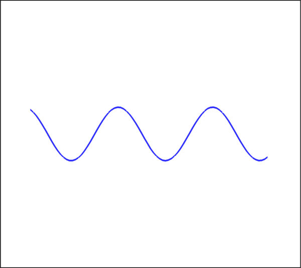
- class tecplot.annotation.Polyline2D(index, mpolyline)[source]
A series of connected points in 2D.
See also
import math

import tecplot as tp
from tecplot.constant import *

# create sine-wave in frame % coordinates
xx = list(range(10, 90))
yy = [10 * math.sin(x / 5) + 50 for x in xx]
points = [(x, y) for x, y in zip(xx, yy)]

frame = tp.active_frame()

line = frame.add_polyline(points, coord_sys=CoordSys.Frame)
line.line_thickness = 2
line.color = Color.Blue

tp.export.save_png('polyline2d.png', 600)
Attributes
Style control for arrowheads.
Index to the associated fieldmap or linemap.
Clip geometry to the axes or frame for 2D plots.
Line
Color.Draw before or after the data.
Background fill color.
Pattern used for drawing lines or edges.
Thickness of lines or edges.
An associated macro function.
Length of the line pattern.
Position coordinate system.
Display annotation in all frames with the same data.
The type of this annotation (read-only).
- Polyline2D.arrowhead
Style control for arrowheads.
Example usage:
>>> from tecplot.constant import ArrowheadAttachment, ArrowheadStyle
>>> polyline.arrowhead.attachment = ArrowheadAttachment.AtEnd
>>> polyline.arrowhead.style = ArrowheadStyle.Filled
- Type:
- Polyline2D.attached_map_index
Index to the associated fieldmap or linemap.
This property allows an annotation to follow the same active/inactive state as another plot object so their visibility can be changed together. Attach this annotation to a fieldmap or linemap using the object’s index property. Geometries and images that are attached to an inactive or non-existent zone are not displayed. Example usage assuming an annotation variable
anno:>>> anno.attached_map_index = plot.fieldmap(2).index
- Polyline2D.clipping
Clip geometry to the axes or frame for 2D plots.
Clipping refers to displaying only that portion of an object that falls within a specified clipping region of the plot. If you have specified the position in the Frame coordinate system, the Annotations will be clipped to the frame. Default:
Clipping.ClipToViewport.If you have specified the Grid coordinate system, you can choose to clip your Annotations to the frame or the viewport. The size of the viewport depends on the plot type as follows:
- 3D Cartesian - The viewport is the same as the frame, so viewport
clipping is the same as frame clipping.
- 2D Cartesian/XY Line - The viewport is defined by the extents of
the X and Y axes.
- Polar Line/Sketch - By default, the viewport is the same as the
frame.
Warning
For 3D and line plots the viewport is the same as the frame and so clipping to the viewport or the frame will have no apparent affect. In cartesian 2D plots, clipping to the axes (
Clipping.ClipToViewport) is only available when the position coordinate system isCoordSys.Grid.Example of clipping a circle to the frame:
>>> from tecplot.constant import Clipping, CoordSys
>>> geom = frame.add_circle((0.5, 0.5), 0.55, CoordSys.Grid)
>>> geom.clipping = Clipping.ClipToFrame
- Type:
- Polyline2D.color
Line
Color.This example shows how to change the edge or line
Colorto red:>>> from tecplot.constant import Color, CoordSys >>> geom = frame.add_circle((50, 50), 10, CoordSys.Frame) >>> geom.color = Color.Red
- Type:
- Polyline2D.draw_order
Draw before or after the data.
Annotations can be drawn either before or after the data. If a geometry or image is drawn before the data, the plot layers, such as mesh, contour lines, etc. will be drawn on top of the geometry. Otherwise, the annotation will be drawn last, potentially obscuring the data.
Note
Tecplot 360 draws all geometries and images first, in the order they were added, then all text.
Example usage assuming an annotation variable
anno:>>> from tecplot.constant import DrawOrder >>> anno.draw_order = DrawOrder.BeforeData
- Type:
- Polyline2D.fill_color
Background fill color.
This example shows how to change the area fill
Colorto red. To turn off filling the geometry, set this attribute toNone:>>> from tecplot.constant import Color, CoordSys >>> geom = frame.add_circle((50, 50), 10, CoordSys.Frame) >>> geom.fill_color = Color.Red
- Type:
- Polyline2D.line_pattern
Pattern used for drawing lines or edges.
This example shows how to change the line pattern:
>>> from tecplot.constant import CoordSys, LinePattern
>>> geom = frame.add_circle((50, 50), 10, CoordSys.Frame)
>>> geom.line_pattern = LinePattern.DashDot
- Type:
- Polyline2D.line_thickness
Thickness of lines or edges.
This example shows how to change the line thickness:
>>> from tecplot.constant import CoordSys
>>> geom = frame.add_circle((50, 50), 10, CoordSys.Frame)
>>> geom.line_thickness = 4.0
- Type:
- Polyline2D.macro_function
An associated macro function.
All geometry or image annotations may be linked to a macro function. This macro function is called when you hold down the Control key (Command key on Mac OS X) and click the right mouse button on the text, geometry or image in the frame.
In order to be attached to a text or geometry object, the macro function must be a “retained” macro function. A macro function is “retained” via either of the following scenarios:
running a macro file that contains the required macro functions
including it in your tecplot.mcr file (which is run at start up, making it a special case of the preceding scenario)
In both cases, the macro function is defined using the $!MACROFUNCTION macro command. Refer to “$!MACROFUNCTION…$!ENDMACROFUNCTION” on page 157 in the Tecplot Macro Scripting Guide for additional information.
Example usage assuming an annotation variable
anno:>>> anno.macro_function = 'MYMACROFUNCTION'
To run this function from PyTecplot it is neccessary to pass the function to a call to
macro.execute_function():>>> tecplot.macro.execute_function(anno.macro_function)
- Type:
- Polyline2D.pattern_length
Length of the line pattern.
This example shows how to change the pattern length:
>>> from tecplot.constant import CoordSys
>>> geom = frame.add_circle((50, 50), 10, CoordSys.Frame)
>>> geom.pattern_length = 1.2
- Type:
- Polyline2D.position
-
This is the origin of the annotation and will be \((x,y)\) or \((\theta,r)\) depending on the plot type. Example usage assuming an annotation variable
anno:>>> anno.position = (3, 4)
- Polyline2D.position_coordinate_system
Position coordinate system.
The object may be positioned using either the grid coordinate system or the frame coordinate system and must be one of
CoordSys.FrameorCoordSys.Grid:CoordSys.Frame: The geometry is always displayed at constant size and position when you zoom in or out of the plot.CoordSys.Grid: The geometry resizes and moves with the data grid. However, the geometry remains fixed when you rotate the plot. Changing the center of rotation may cause the geometry to move.
Example usage assuming an annotation variable
anno:>>> from tecplot.constant import CoordSys >>> anno.position_coordinate_system = CoordSys.Frame
- Type:
- Polyline2D.scope
Display annotation in all frames with the same data.
Annotations with local scope are displayed only in the
Framein which they are created. If it is defined as havingglobalscope, it will appear in all “like”frames. That is, those frames using the same data set as the one in which the annotation was created. (default:Scope.Local)Example usage assuming an annotation variable
anno:>>> from tecplot.constant import Scope >>> anno.scope = Scope.Global
- Type:
- Polyline2D.type
The type of this annotation (read-only).
This is the generic type information for geometry and image annotations. This is a read-only parameter and is used, in combination with position_coordinate_system to determine the actual return types of the iterators
Frame.geometries()andFrame.images():>>> frame.add_image('image.png', (1, 1), 5) >>> frame.add_circle((0,0), 1, CoordSys.Grid) >>> frame.add_square((0,0), 1, CoordSys.Grid) >>> for anno in frame.images(): ... print(anno.type) ... GeomType.Image >>> for anno in frame.geometries(): ... print(anno.type) ... GeomType.Circle GeomType.Square
- Type:
Polyline3D
- class tecplot.annotation.Polyline3D(index, mpolyline)[source]
A series of connected points in 3D.
See also
import math

import tecplot as tp
from tecplot.constant import *

# create helix polyline in data coordinates
zz = [z / 2000 for z in range(1000)]
xx = [0.5 * math.cos(z * 50) for z in zz]
yy = [0.5 * math.sin(z * 50) for z in zz]
points = [(x, y, z) for x, y, z in zip(xx, yy, zz)]

frame = tp.active_frame()
dataset = frame.create_dataset('Dataset Name', ['x', 'y', 'z'])
dataset.add_ordered_zone('Zone Name', (10, 10, 10))
plot = frame.plot(PlotType.Cartesian3D)
plot.activate()

line = frame.add_polyline(points)
line.line_thickness = 2
line.color = Color.Chartreuse

tp.export.save_png('polyline3d.png', 600)

Attributes
Index to the associated fieldmap or linemap.
Line
Color.Background fill color.
Pattern used for drawing lines or edges.
Thickness of lines or edges.
An associated macro function.
Length of the line pattern.
Display annotation in all frames with the same data.
The type of this annotation (read-only).
- Polyline3D.attached_map_index
Index to the associated fieldmap or linemap.
This property allows an annotation to follow the same active/inactive state as another plot object so their visibility can be changed together. Attach this annotation to a fieldmap or linemap using the object’s index property. Geometries and images that are attached to an inactive or non-existent zone are not displayed. Example usage assuming an annotation variable
anno:>>> anno.attached_map_index = plot.fieldmap(2).index
- Polyline3D.color
Line
Color.This example shows how to change the edge or line
Colorto red:>>> from tecplot.constant import Color, CoordSys >>> geom = frame.add_circle((50, 50), 10, CoordSys.Frame) >>> geom.color = Color.Red
- Type:
- Polyline3D.fill_color
Background fill color.
This example shows how to change the area fill
Colorto red. To turn off filling the geometry, set this attribute toNone:>>> from tecplot.constant import Color, CoordSys >>> geom = frame.add_circle((50, 50), 10, CoordSys.Frame) >>> geom.fill_color = Color.Red
- Type:
- Polyline3D.line_pattern
Pattern used for drawing lines or edges.
This example shows how to change the line pattern:
>>> from tecplot.constant import CoordSys, LinePattern
>>> geom = frame.add_circle((50, 50), 10, CoordSys.Frame)
>>> geom.line_pattern = LinePattern.DashDot
- Type:
- Polyline3D.line_thickness
Thickness of lines or edges.
This example shows how to change the line thickness:
>>> from tecplot.constant import CoordSys
>>> geom = frame.add_circle((50, 50), 10, CoordSys.Frame)
>>> geom.line_thickness = 4.0
- Type:
- Polyline3D.macro_function
An associated macro function.
All geometry or image annotations may be linked to a macro function. This macro function is called when you hold down the Control key (Command key on Mac OS X) and click the right mouse button on the text, geometry or image in the frame.
In order to be attached to a text or geometry object, the macro function must be a “retained” macro function. A macro function is “retained” via either of the following scenarios:
running a macro file that contains the required macro functions
including it in your tecplot.mcr file (which is run at start up, making it a special case of the preceding scenario)
In both cases, the macro function is defined using the $!MACROFUNCTION macro command. Refer to “$!MACROFUNCTION…$!ENDMACROFUNCTION” on page 157 in the Tecplot Macro Scripting Guide for additional information.
Example usage assuming an annotation variable
anno:>>> anno.macro_function = 'MYMACROFUNCTION'
To run this function from PyTecplot it is neccessary to pass the function to a call to
macro.execute_function():>>> tecplot.macro.execute_function(anno.macro_function)
- Type:
- Polyline3D.pattern_length
Length of the line pattern.
This example shows how to change the pattern length:
>>> from tecplot.constant import CoordSys
>>> geom = frame.add_circle((50, 50), 10, CoordSys.Frame)
>>> geom.pattern_length = 1.2
- Type:
- Polyline3D.scope
Display annotation in all frames with the same data.
Annotations with local scope are displayed only in the
Framein which they are created. If it is defined as havingglobalscope, it will appear in all “like”frames. That is, those frames using the same data set as the one in which the annotation was created. (default:Scope.Local)Example usage assuming an annotation variable
anno:>>> from tecplot.constant import Scope >>> anno.scope = Scope.Global
- Type:
- Polyline3D.type
The type of this annotation (read-only).
This is the generic type information for geometry and image annotations. This is a read-only parameter and is used, in combination with position_coordinate_system to determine the actual return types of the iterators
Frame.geometries()andFrame.images():>>> frame.add_image('image.png', (1, 1), 5) >>> frame.add_circle((0,0), 1, CoordSys.Grid) >>> frame.add_square((0,0), 1, CoordSys.Grid) >>> for anno in frame.images(): ... print(anno.type) ... GeomType.Image >>> for anno in frame.geometries(): ... print(anno.type) ... GeomType.Circle GeomType.Square
- Type:
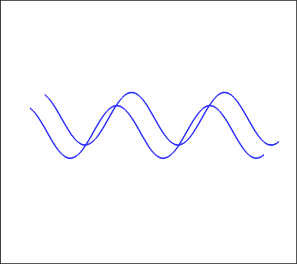
MultiPolyline2D
- class tecplot.annotation.MultiPolyline2D(uid, frame)[source]
A collection of
Polyline2Dobjects.See also
import math

import tecplot as tp
from tecplot.constant import *

# create sine-wave in frame % coordinates
xx = list(range(10, 90))
yy = [10 * math.sin(x / 5) + 50 for x in xx]
points = [(x, y) for x, y in zip(xx, yy)]

# create new line with points shifted up and to the left
shifted_points = [(x + 5, y + 5) for x, y in points]

frame = tp.active_frame()

multi_line = frame.add_polyline(points, shifted_points, coord_sys=CoordSys.Frame)
multi_line.line_thickness = 2
multi_line.color = Color.Blue

tp.export.save_png('multipolyline2d.png', 600)
Attributes
Style control for arrowheads.
Index to the associated fieldmap or linemap.
Clip geometry to the axes or frame for 2D plots.
Line
Color.Draw before or after the data.
Background fill color.
Pattern used for drawing lines or edges.
Thickness of lines or edges.
An associated macro function.
Length of the line pattern.
Position coordinate system.
Display annotation in all frames with the same data.
The type of this annotation (read-only).
- MultiPolyline2D.arrowhead
Style control for arrowheads.
Example usage:
>>> from tecplot.constant import ArrowheadAttachment, ArrowheadStyle
>>> multi_polyline.arrowhead.attachment = ArrowheadAttachment.AtEnd
>>> multi_polyline.arrowhead.style = ArrowheadStyle.Filled
- Type:
- MultiPolyline2D.attached_map_index
Index to the associated fieldmap or linemap.
This property allows an annotation to follow the same active/inactive state as another plot object so their visibility can be changed together. Attach this annotation to a fieldmap or linemap using the object’s index property. Geometries and images that are attached to an inactive or non-existent zone are not displayed. Example usage assuming an annotation variable
anno:>>> anno.attached_map_index = plot.fieldmap(2).index
- MultiPolyline2D.clipping
Clip geometry to the axes or frame for 2D plots.
Clipping refers to displaying only that portion of an object that falls within a specified clipping region of the plot. If you have specified the position in the Frame coordinate system, the Annotations will be clipped to the frame. Default:
Clipping.ClipToViewport.If you have specified the Grid coordinate system, you can choose to clip your Annotations to the frame or the viewport. The size of the viewport depends on the plot type as follows:
- 3D Cartesian - The viewport is the same as the frame, so viewport
clipping is the same as frame clipping.
- 2D Cartesian/XY Line - The viewport is defined by the extents of
the X and Y axes.
- Polar Line/Sketch - By default, the viewport is the same as the
frame.
Warning
For 3D and line plots the viewport is the same as the frame and so clipping to the viewport or the frame will have no apparent affect. In cartesian 2D plots, clipping to the axes (
Clipping.ClipToViewport) is only available when the position coordinate system isCoordSys.Grid.Example of clipping a circle to the frame:
>>> from tecplot.constant import Clipping, CoordSys
>>> geom = frame.add_circle((0.5, 0.5), 0.55, CoordSys.Grid)
>>> geom.clipping = Clipping.ClipToFrame
- Type:
- MultiPolyline2D.color
Line
Color.This example shows how to change the edge or line
Colorto red:>>> from tecplot.constant import Color, CoordSys >>> geom = frame.add_circle((50, 50), 10, CoordSys.Frame) >>> geom.color = Color.Red
- Type:
- MultiPolyline2D.draw_order
Draw before or after the data.
Annotations can be drawn either before or after the data. If a geometry or image is drawn before the data, the plot layers, such as mesh, contour lines, etc. will be drawn on top of the geometry. Otherwise, the annotation will be drawn last, potentially obscuring the data.
Note
Tecplot 360 draws all geometries and images first, in the order they were added, then all text.
Example usage assuming an annotation variable
anno:>>> from tecplot.constant import DrawOrder >>> anno.draw_order = DrawOrder.BeforeData
- Type:
- MultiPolyline2D.fill_color
Background fill color.
This example shows how to change the area fill
Colorto red. To turn off filling the geometry, set this attribute toNone:>>> from tecplot.constant import Color, CoordSys >>> geom = frame.add_circle((50, 50), 10, CoordSys.Frame) >>> geom.fill_color = Color.Red
- Type:
- MultiPolyline2D.line_pattern
Pattern used for drawing lines or edges.
This example shows how to change the line pattern:
>>> from tecplot.constant import CoordSys, LinePattern
>>> geom = frame.add_circle((50, 50), 10, CoordSys.Frame)
>>> geom.line_pattern = LinePattern.DashDot
- Type:
- MultiPolyline2D.line_thickness
Thickness of lines or edges.
This example shows how to change the line thickness:
>>> from tecplot.constant import CoordSys
>>> geom = frame.add_circle((50, 50), 10, CoordSys.Frame)
>>> geom.line_thickness = 4.0
- Type:
- MultiPolyline2D.macro_function
An associated macro function.
All geometry or image annotations may be linked to a macro function. This macro function is called when you hold down the Control key (Command key on Mac OS X) and click the right mouse button on the text, geometry or image in the frame.
In order to be attached to a text or geometry object, the macro function must be a “retained” macro function. A macro function is “retained” via either of the following scenarios:
running a macro file that contains the required macro functions
including it in your tecplot.mcr file (which is run at start up, making it a special case of the preceding scenario)
In both cases, the macro function is defined using the $!MACROFUNCTION macro command. Refer to “$!MACROFUNCTION…$!ENDMACROFUNCTION” on page 157 in the Tecplot Macro Scripting Guide for additional information.
Example usage assuming an annotation variable
anno:>>> anno.macro_function = 'MYMACROFUNCTION'
To run this function from PyTecplot it is neccessary to pass the function to a call to
macro.execute_function():>>> tecplot.macro.execute_function(anno.macro_function)
- Type:
- MultiPolyline2D.pattern_length
Length of the line pattern.
This example shows how to change the pattern length:
>>> from tecplot.constant import CoordSys
>>> geom = frame.add_circle((50, 50), 10, CoordSys.Frame)
>>> geom.pattern_length = 1.2
- Type:
- MultiPolyline2D.position
-
This is the origin of the annotation and will be \((x,y)\) or \((\theta,r)\) depending on the plot type. Example usage assuming an annotation variable
anno:>>> anno.position = (3, 4)
- MultiPolyline2D.position_coordinate_system
Position coordinate system.
The object may be positioned using either the grid coordinate system or the frame coordinate system and must be one of
CoordSys.FrameorCoordSys.Grid:CoordSys.Frame: The geometry is always displayed at constant size and position when you zoom in or out of the plot.CoordSys.Grid: The geometry resizes and moves with the data grid. However, the geometry remains fixed when you rotate the plot. Changing the center of rotation may cause the geometry to move.
Example usage assuming an annotation variable
anno:>>> from tecplot.constant import CoordSys >>> anno.position_coordinate_system = CoordSys.Frame
- Type:
- MultiPolyline2D.scope
Display annotation in all frames with the same data.
Annotations with local scope are displayed only in the
Framein which they are created. If it is defined as havingglobalscope, it will appear in all “like”frames. That is, those frames using the same data set as the one in which the annotation was created. (default:Scope.Local)Example usage assuming an annotation variable
anno:>>> from tecplot.constant import Scope >>> anno.scope = Scope.Global
- Type:
- MultiPolyline2D.type
The type of this annotation (read-only).
This is the generic type information for geometry and image annotations. This is a read-only parameter and is used, in combination with position_coordinate_system to determine the actual return types of the iterators
Frame.geometries()andFrame.images():>>> frame.add_image('image.png', (1, 1), 5) >>> frame.add_circle((0,0), 1, CoordSys.Grid) >>> frame.add_square((0,0), 1, CoordSys.Grid) >>> for anno in frame.images(): ... print(anno.type) ... GeomType.Image >>> for anno in frame.geometries(): ... print(anno.type) ... GeomType.Circle GeomType.Square
- Type:
MultiPolyline3D
- class tecplot.annotation.MultiPolyline3D(uid, frame)[source]
A collection of
Polyline3Dobjects.See also
import math

import tecplot as tp
from tecplot.constant import *

# create double-helix multi-polyline in data coordinates
zz = [z / 2000 for z in range(1000)]
xx = [0.5 * math.cos(z * 50) for z in zz]
yy = [0.5 * math.sin(z * 50) for z in zz]
points = [(x, y, z) for x, y, z in zip(xx, yy, zz)]
points_shifted = [(x, y, z + 0.02) for x, y, z in zip(xx, yy, zz)]

frame = tp.active_frame()
dataset = frame.create_dataset('Dataset Name', ['x', 'y', 'z'])
dataset.add_ordered_zone('Zone Name', (10, 10, 10))
plot = frame.plot(PlotType.Cartesian3D)
plot.activate()

line = frame.add_polyline(points, points_shifted)
line.line_thickness = 2
line.color = Color.Turquoise

tp.export.save_png('multipolyline3d.png', 600)

Attributes
Index to the associated fieldmap or linemap.
Line
Color.Background fill color.
Pattern used for drawing lines or edges.
Thickness of lines or edges.
An associated macro function.
Length of the line pattern.
Display annotation in all frames with the same data.
The type of this annotation (read-only).
- MultiPolyline3D.attached_map_index
Index to the associated fieldmap or linemap.
This property allows an annotation to follow the same active/inactive state as another plot object so their visibility can be changed together. Attach this annotation to a fieldmap or linemap using the object’s index property. Geometries and images that are attached to an inactive or non-existent zone are not displayed. Example usage assuming an annotation variable
anno:>>> anno.attached_map_index = plot.fieldmap(2).index
- MultiPolyline3D.color
Line
Color.This example shows how to change the edge or line
Colorto red:>>> from tecplot.constant import Color, CoordSys >>> geom = frame.add_circle((50, 50), 10, CoordSys.Frame) >>> geom.color = Color.Red
- Type:
- MultiPolyline3D.fill_color
Background fill color.
This example shows how to change the area fill
Colorto red. To turn off filling the geometry, set this attribute toNone:>>> from tecplot.constant import Color, CoordSys >>> geom = frame.add_circle((50, 50), 10, CoordSys.Frame) >>> geom.fill_color = Color.Red
- Type:
- MultiPolyline3D.line_pattern
Pattern used for drawing lines or edges.
This example shows how to change the line pattern:
>>> from tecplot.constant import CoordSys, LinePattern
>>> geom = frame.add_circle((50, 50), 10, CoordSys.Frame)
>>> geom.line_pattern = LinePattern.DashDot
- Type:
- MultiPolyline3D.line_thickness
Thickness of lines or edges.
This example shows how to change the line thickness:
>>> from tecplot.constant import CoordSys
>>> geom = frame.add_circle((50, 50), 10, CoordSys.Frame)
>>> geom.line_thickness = 4.0
- Type:
- MultiPolyline3D.macro_function
An associated macro function.
All geometry or image annotations may be linked to a macro function. This macro function is called when you hold down the Control key (Command key on Mac OS X) and click the right mouse button on the text, geometry or image in the frame.
In order to be attached to a text or geometry object, the macro function must be a “retained” macro function. A macro function is “retained” via either of the following scenarios:
running a macro file that contains the required macro functions
including it in your tecplot.mcr file (which is run at start up, making it a special case of the preceding scenario)
In both cases, the macro function is defined using the $!MACROFUNCTION macro command. Refer to “$!MACROFUNCTION…$!ENDMACROFUNCTION” on page 157 in the Tecplot Macro Scripting Guide for additional information.
Example usage assuming an annotation variable
anno:>>> anno.macro_function = 'MYMACROFUNCTION'
To run this function from PyTecplot it is neccessary to pass the function to a call to
macro.execute_function():>>> tecplot.macro.execute_function(anno.macro_function)
- Type:
- MultiPolyline3D.pattern_length
Length of the line pattern.
This example shows how to change the pattern length:
>>> from tecplot.constant import CoordSys
>>> geom = frame.add_circle((50, 50), 10, CoordSys.Frame)
>>> geom.pattern_length = 1.2
- Type:
- MultiPolyline3D.scope
Display annotation in all frames with the same data.
Annotations with local scope are displayed only in the
Framein which they are created. If it is defined as havingglobalscope, it will appear in all “like”frames. That is, those frames using the same data set as the one in which the annotation was created. (default:Scope.Local)Example usage assuming an annotation variable
anno:>>> from tecplot.constant import Scope >>> anno.scope = Scope.Global
- Type:
- MultiPolyline3D.type
The type of this annotation (read-only).
This is the generic type information for geometry and image annotations. This is a read-only parameter and is used, in combination with position_coordinate_system to determine the actual return types of the iterators
Frame.geometries()andFrame.images():>>> frame.add_image('image.png', (1, 1), 5) >>> frame.add_circle((0,0), 1, CoordSys.Grid) >>> frame.add_square((0,0), 1, CoordSys.Grid) >>> for anno in frame.images(): ... print(anno.type) ... GeomType.Image >>> for anno in frame.geometries(): ... print(anno.type) ... GeomType.Circle GeomType.Square
- Type:
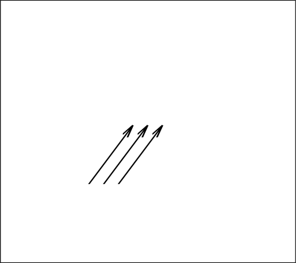
Arrowhead
- class tecplot.annotation.Arrowhead(polyline)[source]
Polyline arrowhead properties.
See also
import tecplot as tp
from tecplot.constant import *

frame = tp.active_frame()

line0 = frame.add_polyline([[30,30], [50,60]], coord_sys=CoordSys.Frame)
line1 = frame.add_polyline([[35,30], [55,60]], coord_sys=CoordSys.Frame)
line2 = frame.add_polyline([[40,30], [60,60]], coord_sys=CoordSys.Frame)

line0.arrowhead.attachment = ArrowheadAttachment.AtEnd
line1.arrowhead.attachment = ArrowheadAttachment.AtEnd
line2.arrowhead.attachment = ArrowheadAttachment.AtEnd

line0.line_thickness = 2
line1.line_thickness = 2
line2.line_thickness = 2

tp.export.save_png('arrowhead.png', 600)
Attributes
The angle of the arrow lines in degrees.
Location of arrowhead on the polyline.
Size of the arrowhead on the polyline.
The style of the arrowhead on the polyline.
- Arrowhead.angle
The angle of the arrow lines in degrees.
This is the angle that one side of the arrowhead makes with the vector, i.e. the apex angle is twice the arrowhead angle:
>>> from tecplot.constant import ArrowheadAttachment
>>> polyline.arrowhead.attachment = ArrowheadAttachment.AtEnd
>>> polyline.arrowhead.angle = 45
- Type:
- Arrowhead.attachment
Location of arrowhead on the polyline.
Possible values are
ArrowheadAttachment.None_,ArrowheadAttachment.AtBeginning,ArrowheadAttachment.AtEndandArrowheadAttachment.AtBothEnds:>>> from tecplot.constant import ArrowheadAttachment >>> polyline.arrowhead.attachment = ArrowheadAttachment.AtEnd
- Type:
- Arrowhead.size
Size of the arrowhead on the polyline.
This is in the coordinate system specified by the
position_coordinate_systemattribute of the polyline:>>> from tecplot.constant import ArrowheadAttachment >>> polyline.arrowhead.attachment = ArrowheadAttachment.AtEnd >>> polyline.arrowhead.size = 10
- Type:
- Arrowhead.style
The style of the arrowhead on the polyline.
Possible values are
ArrowheadStyle.Plain,ArrowheadStyle.HollowandArrowheadStyle.Filled:>>> from tecplot.constant import ArrowheadAttachment, ArrowheadStyle >>> polyline.arrowhead.attachment = ArrowheadAttachment.AtEnd >>> polyline.arrowhead.style = ArrowheadStyle.Filled
- Type:
Images
Image
- class tecplot.annotation.Image(uid, frame)[source]
Image annotation.
This example shows creating an image from a 2D plot and overlaying it on the 3D plot of the same data.
import os

import tecplot as tp
from tecplot.constant import PlotType

examples_dir = tp.session.tecplot_examples_directory()
datafile = os.path.join(examples_dir, 'SimpleData', 'F18.plt')
dataset = tp.data.load_tecplot(datafile)

frame = tp.active_frame()

plot2d = frame.plot(PlotType.Cartesian2D)
plot2d.activate()
plot2d.show_contour = True
plot2d.contour(0).colormap_name = 'Sequential - Blue'
plot2d.contour(0).variable = dataset.variable('S')
tp.export.save_png('embedded_image.png')

plot3d = frame.plot(PlotType.Cartesian3D)
plot3d.activate()
plot3d.show_contour = True
frame.add_image('embedded_image.png', (5, 55), 40)

tp.export.save_png('image.png')

Attributes
Index to the associated fieldmap or linemap.
Draw before or after the data.
Source file (read-only).
Displayed image height in the coordinate system specified.
An associated macro function.
Keep aspect ratio on width or height change.
Position coordinate system.
Original image size in pixels (read-only).
Smoothing filter.
Display annotation in all frames with the same data.
Displayed image size.
The type of this annotation (read-only).
Displayed image width in the coordinate system specified.
Methods
Restore the aspect ratio to that of the original image.
- Image.attached_map_index
Index to the associated fieldmap or linemap.
This property allows an annotation to follow the same active/inactive state as another plot object so their visibility can be changed together. Attach this annotation to a fieldmap or linemap using the object’s index property. Geometries and images that are attached to an inactive or non-existent zone are not displayed. Example usage assuming an annotation variable
anno:>>> anno.attached_map_index = plot.fieldmap(2).index
- Image.draw_order
Draw before or after the data.
Annotations can be drawn either before or after the data. If a geometry or image is drawn before the data, the plot layers, such as mesh, contour lines, etc. will be drawn on top of the geometry. Otherwise, the annotation will be drawn last, potentially obscuring the data.
Note
Tecplot 360 draws all geometries and images first, in the order they were added, then all text.
Example usage assuming an annotation variable
anno:>>> from tecplot.constant import DrawOrder >>> anno.draw_order = DrawOrder.BeforeData
- Type:
- Image.filename
Source file (read-only).
Example usage:
>>> image = frame.add_imge('my_image.png', (20, 20), 40)
>>> print(image.filename)
my_image.png
- Type:
- Image.height
Displayed image height in the coordinate system specified.
The units for height are determined by the
position_coordinate_systemof the image. This example sets the height to 40% of theFrame:>>> from tecplot.constant import CoordSys >>> image.position_coordinate_system = CoordSys.Frame >>> image.height = 40
- Type:
- Image.macro_function
An associated macro function.
All geometry or image annotations may be linked to a macro function. This macro function is called when you hold down the Control key (Command key on Mac OS X) and click the right mouse button on the text, geometry or image in the frame.
In order to be attached to a text or geometry object, the macro function must be a “retained” macro function. A macro function is “retained” via either of the following scenarios:
running a macro file that contains the required macro functions
including it in your tecplot.mcr file (which is run at start up, making it a special case of the preceding scenario)
In both cases, the macro function is defined using the $!MACROFUNCTION macro command. Refer to “$!MACROFUNCTION…$!ENDMACROFUNCTION” on page 157 in the Tecplot Macro Scripting Guide for additional information.
Example usage assuming an annotation variable
anno:>>> anno.macro_function = 'MYMACROFUNCTION'
To run this function from PyTecplot it is neccessary to pass the function to a call to
macro.execute_function():>>> tecplot.macro.execute_function(anno.macro_function)
- Type:
- Image.maintain_aspect_ratio
Keep aspect ratio on width or height change.
Example usage:
>>> image.maintain_aspect_ratio = True
- Type:
- Image.position
-
This is the origin of the annotation and will be \((x,y)\) or \((\theta,r)\) depending on the plot type. Example usage assuming an annotation variable
anno:>>> anno.position = (3, 4)
- Image.position_coordinate_system
Position coordinate system.
The object may be positioned using either the grid coordinate system or the frame coordinate system and must be one of
CoordSys.FrameorCoordSys.Grid:CoordSys.Frame: The geometry is always displayed at constant size and position when you zoom in or out of the plot.CoordSys.Grid: The geometry resizes and moves with the data grid. However, the geometry remains fixed when you rotate the plot. Changing the center of rotation may cause the geometry to move.
Example usage assuming an annotation variable
anno:>>> from tecplot.constant import CoordSys >>> anno.position_coordinate_system = CoordSys.Frame
- Type:
- Image.raw_size
Original image size in pixels (read-only).
Example usage:
>>> print(image.raw_size)
(600, 400)
- Type:
\((width, height)\)
- Image.reset_aspect_ratio()[source]
Restore the aspect ratio to that of the original image.
Example usage:
>>> image.reset_aspect_ratio()
- Image.resize_filter
Smoothing filter.
Possible values are
ImageResizeFilter.Texture,ImageResizeFilter.Box,ImageResizeFilter.Lanczos2,ImageResizeFilter.Lanczos3,ImageResizeFilter.Triangle,ImageResizeFilter.Bell,ImageResizeFilter.BSpline,ImageResizeFilter.Cubic,ImageResizeFilter.Mitchell,ImageResizeFilter.Gaussian. Example usage:>>> from tecplot.constant import ImageResizeFilter >>> image.resize_filter = ImageResizeFilter.BSpline
- Type:
- Image.scope
Display annotation in all frames with the same data.
Annotations with local scope are displayed only in the
Framein which they are created. If it is defined as havingglobalscope, it will appear in all “like”frames. That is, those frames using the same data set as the one in which the annotation was created. (default:Scope.Local)Example usage assuming an annotation variable
anno:>>> from tecplot.constant import Scope >>> anno.scope = Scope.Global
- Type:
- Image.size
Displayed image size.
This will be in the coordinates specified by
Image.position_coordinate_system. Example usage:>>> image.size = (40, 20)
- Type:
\((width, height)\)
- Image.type
The type of this annotation (read-only).
This is the generic type information for geometry and image annotations. This is a read-only parameter and is used, in combination with position_coordinate_system to determine the actual return types of the iterators
Frame.geometries()andFrame.images():>>> frame.add_image('image.png', (1, 1), 5) >>> frame.add_circle((0,0), 1, CoordSys.Grid) >>> frame.add_square((0,0), 1, CoordSys.Grid) >>> for anno in frame.images(): ... print(anno.type) ... GeomType.Image >>> for anno in frame.geometries(): ... print(anno.type) ... GeomType.Circle GeomType.Square
- Type:
- Image.width
Displayed image width in the coordinate system specified.
The units for width are determined by the
position_coordinate_systemof the image. This example sets the width to 40% of theFrame:>>> from tecplot.constant import CoordSys >>> image.position_coordinate_system = CoordSys.Frame >>> image.width = 0.4
- Type:
GeoreferencedImage
- class tecplot.annotation.GeoreferencedImage(uid, frame)[source]
A Geographic reference image.
A georeferenced can be added to a plot with a call to
Frame.add_georeferenced_image(). Placement of the image is controlled by the \((x, y)\) variables of theFrameand theGeoreferencedImageobject’s \(z\) parameter.Attributes
Index to the associated fieldmap or linemap.
An associated macro function.
Display annotation in all frames with the same data.
The type of this annotation (read-only).
\(z\)-position of the georeferenced image.
- GeoreferencedImage.attached_map_index
Index to the associated fieldmap or linemap.
This property allows an annotation to follow the same active/inactive state as another plot object so their visibility can be changed together. Attach this annotation to a fieldmap or linemap using the object’s index property. Geometries and images that are attached to an inactive or non-existent zone are not displayed. Example usage assuming an annotation variable
anno:>>> anno.attached_map_index = plot.fieldmap(2).index
- GeoreferencedImage.macro_function
An associated macro function.
All geometry or image annotations may be linked to a macro function. This macro function is called when you hold down the Control key (Command key on Mac OS X) and click the right mouse button on the text, geometry or image in the frame.
In order to be attached to a text or geometry object, the macro function must be a “retained” macro function. A macro function is “retained” via either of the following scenarios:
running a macro file that contains the required macro functions
including it in your tecplot.mcr file (which is run at start up, making it a special case of the preceding scenario)
In both cases, the macro function is defined using the $!MACROFUNCTION macro command. Refer to “$!MACROFUNCTION…$!ENDMACROFUNCTION” on page 157 in the Tecplot Macro Scripting Guide for additional information.
Example usage assuming an annotation variable
anno:>>> anno.macro_function = 'MYMACROFUNCTION'
To run this function from PyTecplot it is neccessary to pass the function to a call to
macro.execute_function():>>> tecplot.macro.execute_function(anno.macro_function)
- Type:
- GeoreferencedImage.scope
Display annotation in all frames with the same data.
Annotations with local scope are displayed only in the
Framein which they are created. If it is defined as havingglobalscope, it will appear in all “like”frames. That is, those frames using the same data set as the one in which the annotation was created. (default:Scope.Local)Example usage assuming an annotation variable
anno:>>> from tecplot.constant import Scope >>> anno.scope = Scope.Global
- Type:
- GeoreferencedImage.type
The type of this annotation (read-only).
This is the generic type information for geometry and image annotations. This is a read-only parameter and is used, in combination with position_coordinate_system to determine the actual return types of the iterators
Frame.geometries()andFrame.images():>>> frame.add_image('image.png', (1, 1), 5) >>> frame.add_circle((0,0), 1, CoordSys.Grid) >>> frame.add_square((0,0), 1, CoordSys.Grid) >>> for anno in frame.images(): ... print(anno.type) ... GeomType.Image >>> for anno in frame.geometries(): ... print(anno.type) ... GeomType.Circle GeomType.Square
- Type: