21 - 7 Performing Integrations
Tecplot 360 EX provides a flexible integration feature. You can integrate scalar dataset variables as well as vector variables dotted with grid unit normal or unit tangential vectors, and you can integrate by zone in a single time step, or by time strand. Tecplot 360 EX also has several pre-defined integrations, such as mass flux, which simplify the integration process. In ordered zones, you can integrate these quantities over cell volumes, face areas, or lines. In finite element zones, you can integrate over cell volumes. In addition, you can calculate lift, drag, side force and moments due to pressure and viscous forces acting on a surface or a set of surfaces.
|
|
 The Integration feature refers to cell volumes in its user interface. In 2D or 1D zones, the cell area or length, respectively, is used in place of the volume.
The results of the integration may be displayed in a text window (and subsequently saved to a text file), or plotted in a frame. In the latter case, the solution time of the integration plot's frame is linked to the original frame's solution time and a marker gridline is displayed on the integration plot to indicate the time step. All of these features are accessed via the Integrate dialog (accessed via Analyze>Perform Integration).
|
|
 Many of these calculations are affected by settings in the
 Integrations of a variable or variable function use the trapezoidal method, and are second-order accurate. For each segment, face, or volume cell, the appropriate nodal or cell-centered values are averaged and multiplied by the cell length, area or volume. The calculation sums the resulting quantities over the zone or specified subset to produce the integrated result.
The Integrate dialog is displayed by selecting Perform Integration from the Analyze menu.
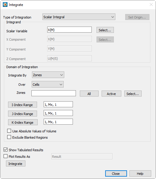
The resulting dialog provides options to specify the zone(s) of integration, the variable to be integrated, the domain of integration and display methods.
• Type of Integration - Tecplot 360 EX can perform simple, path, surface, and volume integrals. Refer to Integrate Over to see how to select these using the current plot type. Tecplot 360 EX defines the following fourteen integration types:
• Length/area/volume - The physical size of the integration domain.
• Scalar - The integral of a single variable.
• Average - The area or volume-weighted average of a single variable over the domain.
• Mass weighted scalar - The integral of a single variable multiplied by density.
• Mass weighted average - The weighted average of a single variable, with density as the weighting function.
• Weighted average - A general weighted average—both the variable and the weighting function are specified.
• Scalar flow rate - The convection of a scalar through a surface. It is calculated by integrating the dot product of the flow velocity and the surface unit normal multiplied by the scalar variable.
• Mass flow rate - The convection of density through a surface. This is calculated by integrating the dot product of the flow velocity and the surface unit normal multiplied by the density.
• Mass weighted flow rate - The convection of a scalar multiplied by density through a surface. This is calculated by integrating the dot product of the flow velocity and the surface unit normal multiplied by the scalar variable and density.
• Mass flow weighted average - The weighted average of a scalar variable on a surface. Here the weighting function is the dot product of the flow momentum vector (velocity multiplied by density) and the surface unit normal.
• Forces and moments - The integral of pressure and viscous stresses on a surface. The Forces and Moments option integrates pressure and shear stresses over lines (2D) and planes (3D). Pressure is assumed to act in the opposite direction of the unit normals. These are calculated by integrating the dot product of the stress tensor and the surface unit normal. This will correctly calculate lift and drag if, for example, you have a 2D airfoil defined by the J=1 line and you integrate forces and moments over I-lines (or J-planes) for J=1.
For proper calculation of viscous forces, make sure you have set the value of viscosity in the Fluid Properties dialog. (See “Specifying Fluid Properties” on page 325.) If your flow is inviscid, you should exclude viscous forces from the integration by setting viscosity to zero.
Forces and Moments are calculated as six quantities: X, Y and Z-Force and X, Y and Z-moments about the origin. For backward compatibility, the forces are also displayed as Lift, Drag and Side force. Lift and Drag are the forces rotated in the XY-plane such that Lift is normal to the reference flow direction (specified on the Reference Values dialog) and Drag is parallel to it. Side force is equal to Z-Force.
If an I-ordered zone (in 2D) or a surface zone (in 3D) has been defined as a boundary to a surface (2D) or volume (3D) zone, then you can perform a Forces and Moments integration over this boundary zone. Tecplot 360 EX takes the shear stress and unit normal direction from the associated zone. This allows you, for example, to perform Forces and Moments integrations for finite element solutions, provided you have a line or surface zone that defines the surface, and you have identified this zone as a boundary zone in the Geometry and Boundaries dialog.
• Vector-dot-normal - The integral over a surface of a vector dotted with the surface unit normals. Here the components of the vector are dataset variables.
• Vector average - The weighted average of a scalar variable on a surface. The weighting function is the dot product of a vector with the surface unit normal. Both the scalar and the vector components are dataset variables.
• Vector-dot-tangential - The integral on a line of a specified vector dotted with the line unit tangential vector.
|
If you have selected the 2D Cartesian plot type and have specified that the geometry is axisymmetric, an axisymmetric integration will be performed. Tecplot 360 EX multiplies each grid segment's or cell's contribution to the integration by Integrations involving surface unit normals, such as Mass Flow Rate and Forces and Moments integration, rely on surface unit normals pointing in a consistent direction (that is, toward the same side of the surface zone). This is guaranteed for ordered surface zones, but not for finite element surface zones (triangular, quadrilateral, or polygonal), including extracted slices. For these zones, the surface unit normal direction for each face is calculated using the right-hand rule with the node order for the face. If the nodes for some faces progress clockwise around the face while other faces' nodes progress counter-clockwise (as defined by the zone's connectivity), the faces' surface normals will point in inconsistent directions, and any integration that relies on these normals will not produce meaningful results. You can check for this condition using the technique for visualizing surface unit normals described in Section 21 - 6.6 “Surface Normal Calculations”. Similarly, an integration that sums results from multiple surface zones may not be meaningful because the normals from one zone may be inconsistent with the normals of some other zone. |
 Options that involve a unit normal must be integrated over a domain where the unit normal direction can be determined. Acceptable domains include lines in 2D or planes in 3D, as well as triangular or quadrilateral zones in 3D. The vector-dot-tangential options can only be integrated over lines. Unit normals are discussed further in
  , where
  is the distance from the centroid of the segment or cell to the axis of symmetry.
• Integrand - Some of the available types of integrations require you to choose variables from your dataset to be integrated. Where required, fields in the Integrand section of the dialog will be enabled. You may type in the variable names, or click Select to choose variables.
For Forces and Moments integrations, pressure and the components of velocity are calculated from the field variables identified on the Field Variables dialog.
• Specifying the Domain of Integration - The domain of integration is defined by zone or time strand numbers and index ranges. For ordered zones, you may choose whether to integrate over lines, planes, or volumes. You may also choose to use the absolute value of calculated volumes, which can be useful for finite element zones where the node ordering may result in erroneous calculations. Finally, you can choose to exclude regions not displayed due to index or value blanking. Please refer to Chapter 19: “Blanking” for more information on blanking.
• Integrate By
The Integrate By drop-down menu lets you specify whether to integrate over specific zones or specific time strands.
The Over drop-down menu allows you to specify cells, planes of constant I, J, or K, or lines of varying I, J, or K. For tetrahedral and brick finite element zones, only volume integration is allowed. For quadrilateral and triangular finite element zones, only K-planes are allowed (selecting Cells for these zones is equivalent to selecting K-planes, since they are logically 2D). For 2D and 3D Cartesian plot types, integrations over lines are performed as path integrals and integrals over planes are performed as surface integrals. Integrals in XY line plots integrate the chosen variable along the X axis to calculate the area between the curve and the X axis. Volume integrations should be done in 3D Cartesian plots—volume integrations in 2D Cartesian plots will give zero results.
If a vector dot product is to be integrated, then the domain must have an identifiable normal or tangential direction. In 3D Cartesian plots, this usually means I, J, or K-planes will be selected. The normals in these cases will point in the +I, +J, and +K-directions, respectively, or the reverse for a left-handed grid. I,I, J, and K-planes do not have an identifiable tangential direction, so vector-dot-tangential integration over planes generates an error.
If I, J, or K-Lines are selected, the tangential vectors point in the positive-index direction. Vector-dot-normal integration is also available, but may not be meaningful—the normal is calculated by taking the cross-product of the tangential and the +Z-axis.
In 2D Cartesian plots, I-planes are equivalent to J-lines, J-planes is equivalent to I-lines, and K-planes is equivalent to cells. (It may be better to ignore planes in two dimensions.) Both normal and tangential directions are available in all cases. However, the normal to K-planes points in the third dimension; it may not be meaningful.
For quadrilateral and triangular finite element zones, the normal direction is found with the right-hand rule—if the fingers of the right hand are curled in the direction of a line drawn from cell node 1 to node 2, thence to node 3, then the thumb will point in the direction of the normal.
• Zones/Time Strands - Depending on whether you have chosen to integrate by zones or by time strands, this text field allows you to specify which zones or time strands the variable will be integrated over. You may enter a single zone or strand, a range with a hyphen (for example, 3-5), or a combination of these, separated by commas (,). For convenience, the [All] button will set this text field to indicate all zones or time strands. The [Active] button will list all zones or time strands currently active. You may also select items from a list by clicking Select, which calls up a separate selection dialog.
• Specifying Index Ranges - Below the Zone or Time Step field are I, J, and K-index ranges. These ranges will be applied to each zone over which the integration is performed. The three comma separated items in each index range indicate the starting index, the ending index and the skip factor, respectively.
For finite element zones, only the J-index settings have effect. These indicate the range of cells over which the integration will be performed. For reasons discussed below, a skip factor of 1 is probably desirable for these cases.
To enter or change an index range, select the button over the desired range's text field. The Enter Range dialog will be displayed.
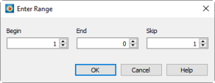
Enter the starting index in the Begin field, the ending index in the End field, and the skip factor in the Skip field.
You have two options for entries into the End field. You can enter a number, in which case the maximum allowable value is displayed at the top of this dialog, and indicates the smallest size of the given index for all of the zones listed on the Integrate dialog. Alternatively, you can enter "Mx" to use the maximum index for each individual zone, "Mx - 1" to use one less than the maximum and so on. A skip factor of 1 means "use every point in the range," a skip of two means, "use every other point", and so forth.
For linear and planar integration, skip factors are ignored along the line, or within the plane of integration. For example, if you are integrating along I-lines, the I-skip factor will be ignored. If you are integrating along an IJ-plane (for example), both I- and J- skip factors are ignored. For volume cells, all skip factors are ignored. Minimum and maximum index values are always used.
• Time Min/Max - When integrating by time strands, these fields appear to the right of the Index Range, allowing you to specify the starting and ending time steps for the integration. Click the Reset Min/Max button to set these fields to the first and last time steps in your data set, respectively.
• Use Absolute Values of Volume - Takes the absolute value of the volumes of 3D grid cells used for integration. This is useful if you have a finite element grid with arbitrary node ordering such that the calculated volume of cells may be positive or negative. Negative grid cell volumes occur when left-handed grids are used in Tecplot 360 EX. A right-handed ordered zone will have the +J-direction proceeding to the left of the +I-direction when viewed from the +K-direction. For finite element zones, the nodes of each cell will proceed counter-clockwise when viewed from the direction of the highest-numbered node.
• Exclude Blanked Regions - Removes from the integration domain portions of any zones that are hidden due to value or index-blanking. (Note that 3D depth blanking has no effect.)
Excluding blanked regions can lead to unexpected results, depending on the blanking settings. In particular, note that blanking options allow for a cell to be blanked when any of its nodes is blanked, when its "primary" (or lowest-numbered) index is blanked, or only when all of its nodes are blanked. As a result, cells may still be displayed where some nodes have been blanked. Figure 21-11 illustrates this effect. Index-blanking has been used to blank all nodes along the J=1 line, but all cells are still displayed. An integration over volumes or K-planes would include the entire mesh, while integrations over I-lines or J-lines would exclude the J=1 line. In general, display the Mesh layer to see the domain of integration if you are integrating over volumes in 3D or planes in 2D, and display the Scatter layer to see the remaining types of integration domain. See Chapter 19: “Blanking” for more information on blanking.
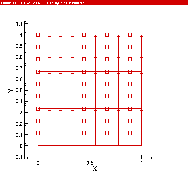
Figure 21-11. The effect of blanking on nodes and cells.
• Performing the Integration - Selecting Integrate at the bottom of the Integrate dialog will perform the integration and display the results. Tecplot 360 EX uses the trapezoidal method, a second-order method which averages nodal values to cell, face, or edge centers, then sums the products of these values with the corresponding cell volumes, areas, or lengths.