Tecplot 360 EX includes the ability to load input and solution files from many popular finite element analysis (FEA) solvers. Supported formats include:
|
Solver/File Format |
File Name/Extension |
|---|---|
|
3D Systems STL |
.stl |
|
ABAQUS Data |
.fil |
|
ABAQUS Input |
.inp |
|
ABAQUS Output Database |
.odb |
|
ANSYS CDWRITE Input |
.cdb |
|
ANSYS CFX |
.res |
|
ANSYS Result |
.rst,.rth,.rfl |
|
LSTC-DYNA Input |
.dyn,.k |
|
LSTC-DYNA Taurus State |
D3PLOT |
|
MSC/NASTRAN Bulk Data |
.bdf |
|
MSC/NASTRAN Output2 |
.op2 |
|
MSC/PATRAN Neutral |
.out |
|
OpenFOAM |
controlDict |
|
PTC/Mechanica Design Study |
.neu |
|
SDRC/IDEAS Universal |
.unv |
The file formats supported for each solver's formats are:
|
Solver |
Version |
|---|---|
|
3D Systems STL |
all |
|
ABAQUS |
up to 2021 |
|
ANSYS |
up to 2021 R1 |
|
ANSYS CFX |
up to 2021 R1 |
|
LST-DYNA |
up to 970.0 |
|
MSC/NASTRAN |
up to 2018 |
|
OpenFOAM |
2.0, including compressed files |
|
PTC/Mechanica Wildfire |
up to 4.0 |
|
SDRC/IDEAS NX |
up to Series 11 |
4 - 11.1 Format-Specific Notes
ABAQUS Output Database files are supported on Windows only. Other ABAQUS formats are supported on all platforms.
Abaqus .odb files from older versions will be converted to the current format before being loaded through the user interface. However, this conversion will not occur automatically for files loaded with a layout file or via a macro command. To work around this, you will need to convert the older .odb file by loading it explicitly and saving the new .odb file. Then replace the file names in their layouts/macros with the new names using a text editor.
Von Mises stress data is loaded for NASTRAN data files that contain it. The FEA loader also can load both cell-centered and nodal data from NASTRAN files. This ability was added in Tecplot 360 EX 2016 R3 and may cause macros and layouts that refer to variables by number to choose the wrong variable. A warning will appear when loading such files. To address the warning, re-create the layout or macro, or else update the style settings as necessary and change the !$READDATASET instruction in the layout or macro to include the parameter "FEALoaderVersion" "436".
FEA formats have "(FEA)" appended to the format names in the Load Data dialog. Choosing to open a selected file using the FEA loader's advanced options displays a dialog like the one below. The dialog shown is for the ANSYS Result file format, but all formats use the same dialog (only the file format, displayed in the dialog's title bar, differs)
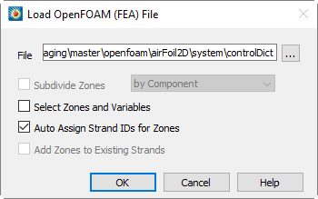
.
• Click the Browse [...] button to change the file you wish to load. By default, it is the file you selected in the Load Data dialog.
|
|
 For OpenFOAM cases, load the
 • Subdividing Zones - Each zone loaded from an FEA file typically represents the entire solution at a particular time step or load increment. Sometimes a solution will consist of many components that you may wish to display individually. To activate this option, choose the "Subdivide Zones" toggle and select the desired subdivision option from the menu. Tecplot 360 EX provides you with two ways to subdivide zones: by Component and by Element Type.
• Subdividing Zones by Component - Some FEA file formats include the ability to identify components or sub-regions. If this information is available, you may direct Tecplot 360 EX to apply it by selecting the "by Component" option. Components within each solution step will be identified by sequentially numbered zone names in Tecplot 360 EX, for example, "Component 1 Step 1 Incr 1," "Component 2 Step 1 Incr 1," and so on.
• Subdividing Zones by Element Type - If component information is not available in a solution file, the above option will produce only one component per solution step and increment. In this case, it may still be possible to achieve the desired effect if sub-regions in the solution are represented by different element types, such as shell elements and brick elements. Selecting "by Element Type" from the subdivision option menu creates a separate Tecplot zone for each element type present in the solution file. Tecplot zone names will then represent each element type, for example, "Quadrilaterals Step 1 Incr 1" and "Tetrahedrals Step 1 Incr 1." This makes it easy to operate on individual components or sub-regions in Tecplot 360 EX's Zone Style dialog by selecting the desired zones by name.
• Selecting Zones and Variables to Load - See Selecting Zones and Variables to Load .
• Auto Assign Strand IDs for Zones - Regions or components of solutions throughout an unsteady solution are tracked by Strand IDs. All zones that represent a particular region or component are assigned the same Strand ID. Selecting this option directs Tecplot 360 EX to assign Strand IDs to the loaded zones. This ensures that only the zones representing the chosen solution time are displayed in Tecplot 360 EX. Zones that do not have Strand IDs assigned are displayed at all solution times. See also Section 7 - 2 “Time Aware”.
• Add Zones to Existing Strands - If you are appending data to an existing dataset, select Add Zones to Existing Strands to append the new zones to existing strands. This is appropriate where the new data represents the same regions or components as are represented in the existing dataset, such as an additional solution time level of an unsteady solution.