21 - 4.3 The Edit Boundary dialog
The Edit Boundary dialog is displayed by clicking New on the Geometry and Boundaries dialog, or by selecting an existing boundary and then selecting Edit.
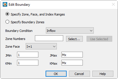
It allows you to identify a boundary of one or more zones, either by entering the zone number(s), face and index range on that face, or by entering the zone numbers of boundary zones, as discussed in Section 21 - 4 “Setting Geometry and Boundary Options”. Enter the desired options and select [OK] to add the boundary to the Geometry and Boundaries dialog.
Using Index Range-type Boundaries
For ordered zones, you may identify boundary regions by choosing a zone boundary, or face, and index ranges to specify a region on the face. To create an index range-type boundary, select Zone, Face and Index Range, and choose the desired boundary condition from the Boundary Condition drop-down menu. Select the zones to which this boundary will apply by entering their zone numbers in the Zone Numbers text field, or clicking [Select] and choosing the zones from the resulting dialog. (See Section 21 - 7 “Performing Integrations” for a description of the Select Zones dialog.) If you have selected zones by clicking in the work space, you may enter these zone numbers by clicking Use Selected. Choose a face from the Zone Face drop-down and enter the index ranges in the remaining text fields. When you select [OK], the new boundary will appear in the Boundaries list in the following format:
<bc>,<set>,<face>,INDEX1MIN,INDEX1MAX,INDEX2MIN,INDEX2MAX
<bc> is the boundary condition, one of Inflow, Outflow, Wall, Slipwall, Symmetry, and Extrapolated. <set> is the set of zone numbers to which the boundary applies, enclosed in square brackets. <face> is one of I=1, I=IMAX, J=1, J=JMAX, K=1, and K=KMAX and the remaining parameters are the minimum and maximum indices on the face, with zero indicating the maximum index value, and negative numbers indicating offsets from the maximum index value. For example, the following line would indicate a wall boundary condition set on the J = 1 face of zones 2, 4, 5, and 6 from I = 1 to IMax and K = 3 to KMax - 2:
Wall,[2,4-6],J=1,1,0,3,-2
Using Boundary Zone-Type Boundaries
For all zone types, you may identify boundary zones, as discussed in Section 21 - 4 “Setting Geometry and Boundary Options”. Toggle-on Specify Boundary Zones and choose the desired boundary condition from the Boundary Condition drop-down menu. Enter the zone numbers of the boundary zones, or click Select and choose them from the resulting dialog. The boundary will be applied to any volume (3D) or surface (2D) zones in the dataset. The boundary appears in the Boundaries list in the following format:
<bc>,<set>
where <bc> is as described above, and <set> is the set of boundary zones that define the boundary.